|
STEP
|
INSPECTION
|
ACTION
|
|
|---|---|---|---|
|
1
|
INSPECT ALARM ACTIVATION
Set the theft-deterrent alarm. After the alarm is set, open the driver-saide door to trigger the alarm.
Is there an alarm output function inoperative?
|
Yes
|
If the hazard warning lights do not flash, Go to the next step.
If the horn does not cycle, Go to Step 3.
|
|
No
|
The alarm outputs are functioning correctly.
Inspect the system for normal operation.
|
||
|
2
|
INSPECT HAZARD WARNING LIGHTS CIRCUIT
Turn the ignition switch to the ON position.
Connect a jumper wire between GEM connector terminal 1Q (harness-side) and ground.
Do the hazard warning lights come on?
|
Yes
|
Go to the next step.
|
|
No
|
|||
|
3
|
INSPECT HORN OPERATION
Connect the GEM connector.
Turn the ignition switch to the ON position.
Operate the horn from the horn switch.
Does the horn operate?
|
Yes
|
Go to the next step.
|
|
No
|
|||
|
4
|
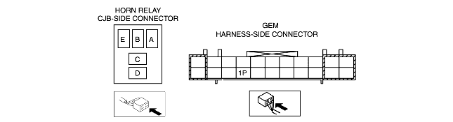
INSPECT CIRCUIT BETWEEN HORN RELAY AND GEM
Disconnect the GEM connector.
Disconnect the horn relay connector.
Measure the resistance between GEM connector terminal 1P (harness-side) and horn relay terminal A (CJB-side).
Is the resistance less than 5 ohms?
|
Yes
|
Go to the next step.
|
|
No
|
Repair the circuit.
Inspect the system for normal operation.
|
||
|
5
|
INSPECT GEM FOR NORMAL OPERATION
Disconnect the all GEM connectors.
Inspect for the following items:
• Corrosion
• Terminal separation
Connect all the connectors and verify that their positions are correct.
Operate the system and inspect for any malfunction.
Is there any malfunction?
|
Yes
|
Install a new GEM. (See GENERIC ELECTRONIC MODULE (GEM) REMOVAL/INSTALLATION.)
Clear the DTC and perform the DTC inspection.
|
|
No
|
Verify that the system operates normally at this stage. The malfunction may result from loose connectors or corrosion.
Clear the DTC and perform the DTC inspection.
|
||
|
|
|||