1. Inspect the speedometer using check code 12 of the input/output check mode. (See INPUT/OUTPUT CHECK MODE OF INSTRUMENT CLUSTER [L3].)
1. Adjust the tire pressure to the specification.
2. Using a speedometer tester, verify that the tester reading is as indicated in the table.
|
Speedometer tester indication (km/h)
|
Allowable range (km/h)
|
|
20
|
19-21
|
|
40
|
39-42
|
|
60
|
59-63
|
|
80
|
79-83
|
|
100
|
100-104
|
|
120
|
120-125
|
|
140
|
140-145
|
3. Verify that the speedometer reading is within the range indicated in the table.
1. Inspect the tachometer using check code 13 of the input/output check mode. (See INPUT/OUTPUT CHECK MODE OF INSTRUMENT CLUSTER [L3].)
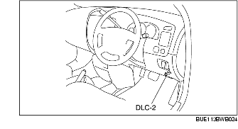
1. Connect the WDS or equivalent to the DLC-2 (16-pin).
2. Compare the RPM with the tachometer indication.
1. Inspect the fuel gauge using check code 23 of the input/output check mode. (See INPUT/OUTPUT CHECK MODE OF INSTRUMENT CLUSTER [L3].)
1. Inspect the water temperature gauge using check code 25 of the input/output check mode. (See INPUT/OUTPUT CHECK MODE OF INSTRUMENT CLUSTER [L3].)