Spring Plate
A/C COMPRESSOR MODEL No.350
Note: The spring plate, the clutch body with pulley and the magnetic coil, as well as the shaft seal can only be removed and installed with refrigerant compressor removed.
The clutch body forms a single assembly together with bearing, pulley and magnetic coil. If one component of this assembly group must be replaced, remove the complete assembly group.
Removal:
1. Remove a/c compressor.
2. Attach retaining device to the a/c compressor and clamp in vice. Then seal openings with presure test plate.
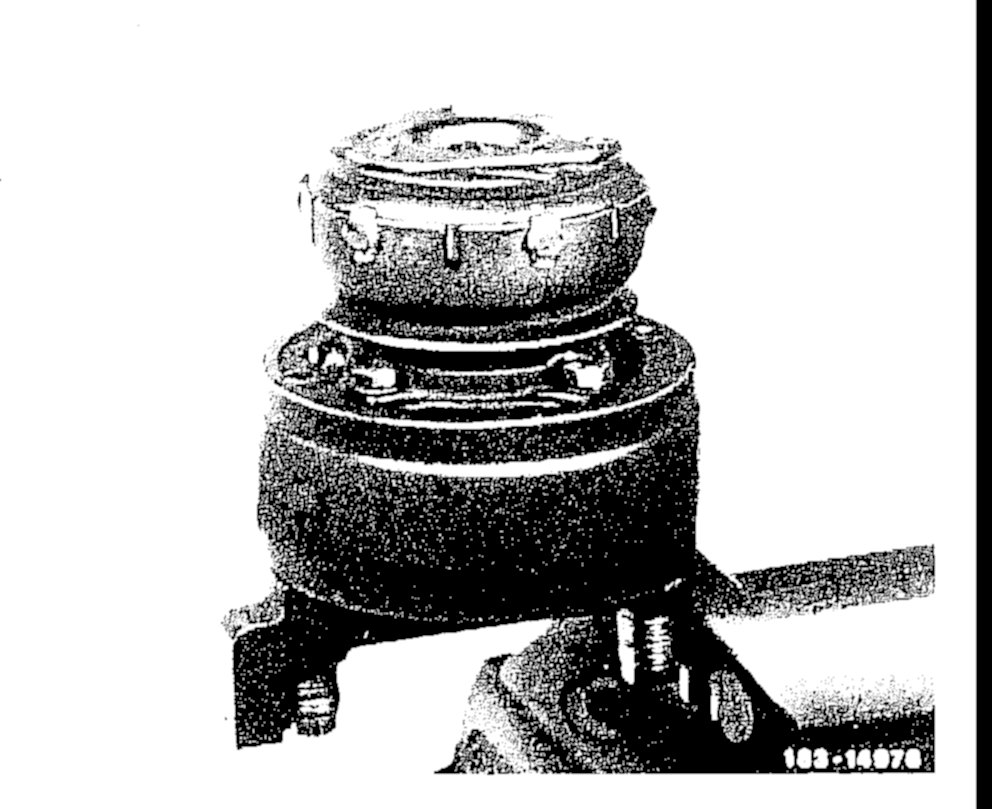
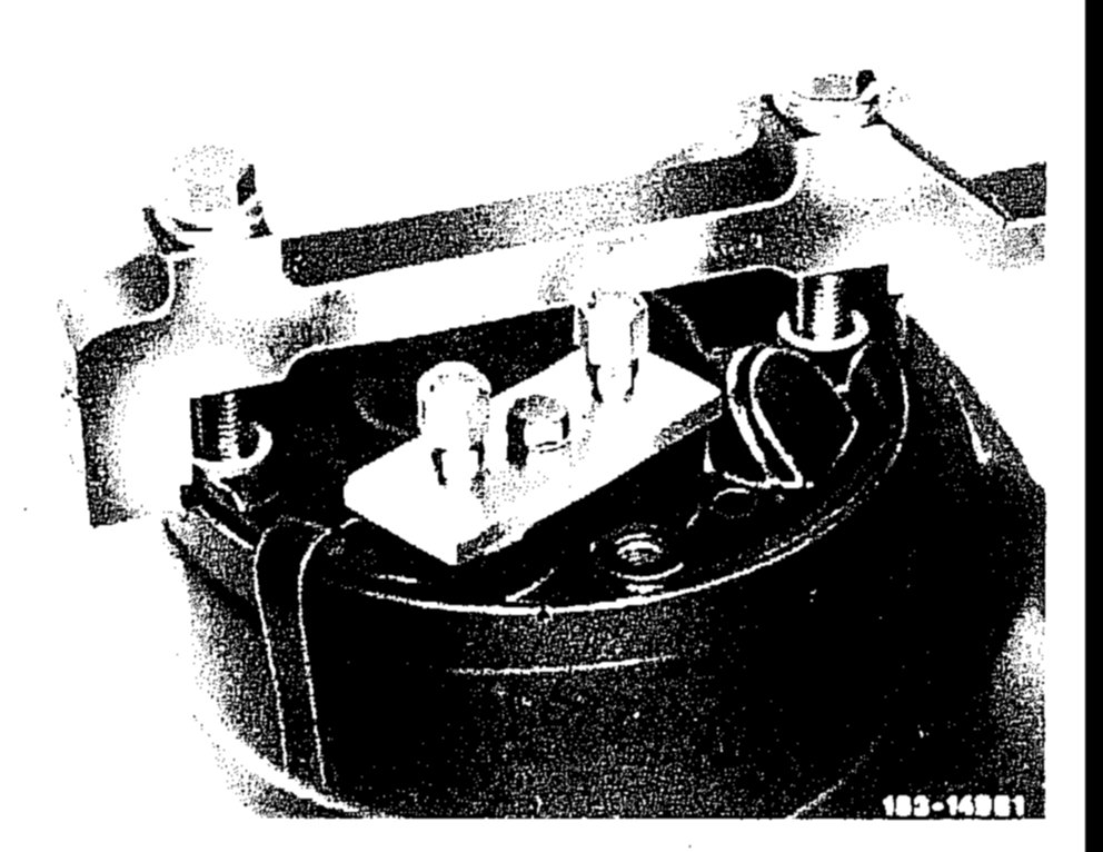
3. Remove a/c compressor from the retaining device, then clamp in again with the drive shaft pointing upward.
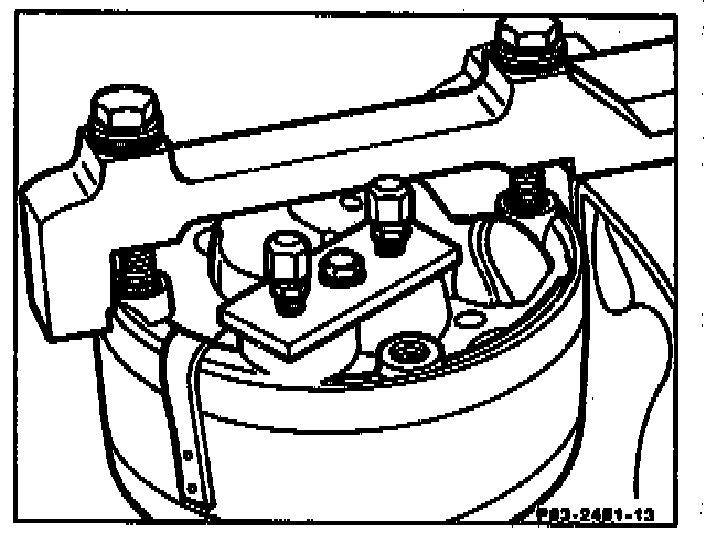
Repair Notes: Measure the distance between spring plate and crankshaft before replacing the spring plate (see illustrations below). Only spring plates of the same version as the original are to be installed. For A/C compressor Model No.627 see section below.
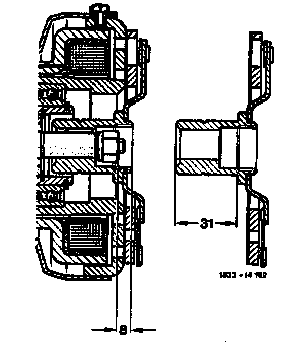
Version on a/c compressor Model No.350
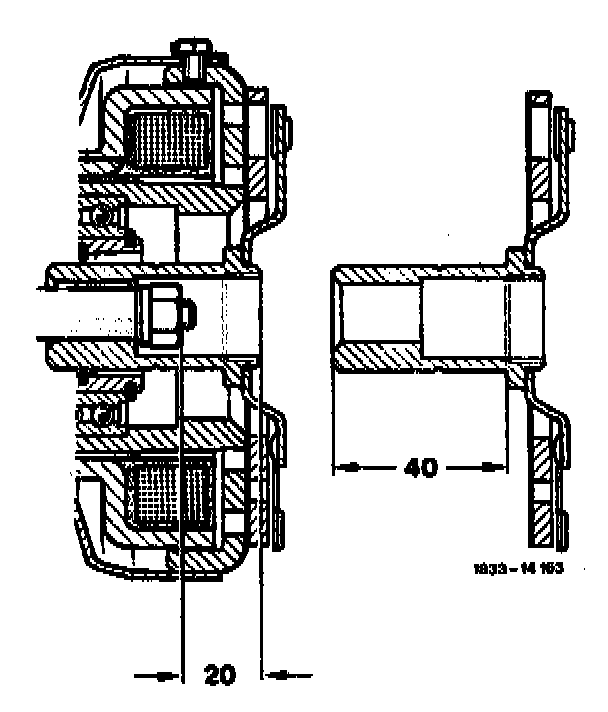
Version on a/c compressor Model No.627
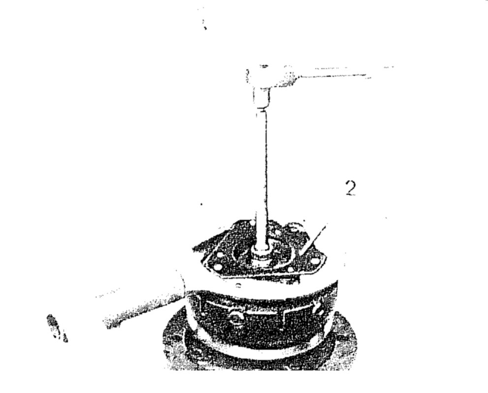
4. Turn wrench to prevent the spring plate (2) from turning, unscrew nut from shaft with 14 mm socket.
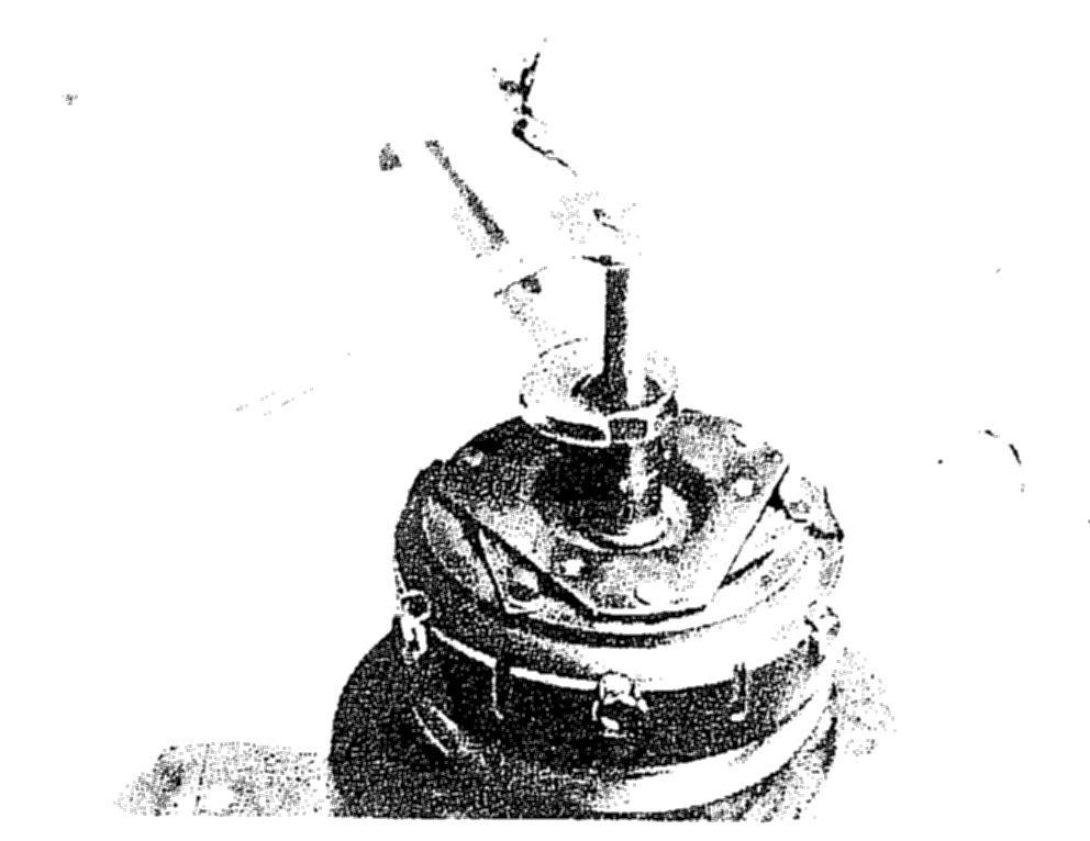
5. Screw removal tool into the hub, hold the tool in place with wrench and tighten the center bolt
6. Remove key from the shaft.
Installation:
7. Clean friction surfaces of spring plate and clutch body.
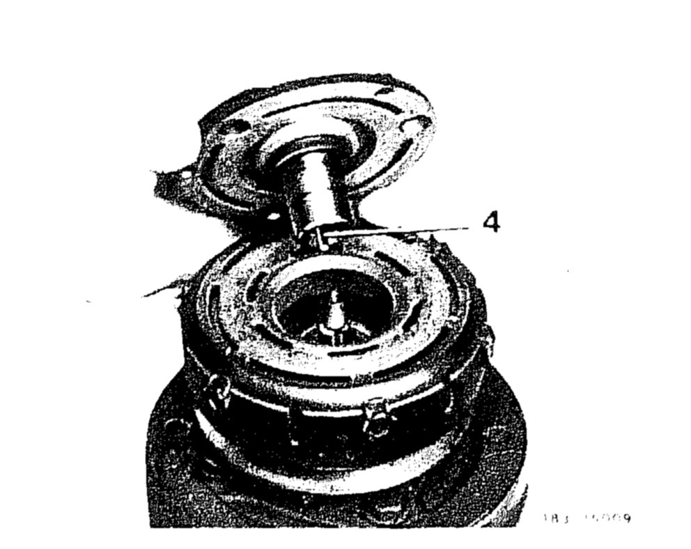
8. Insert key (4) in the hub so that it protrudes by approx. 5 mm.
9. Place spring plate on the shaft so that key and key groove are in alignment.
10. Place spacer on the spring plate. Insert assembly tool through the spacer and screw the assembly tool to the end of the shaft.
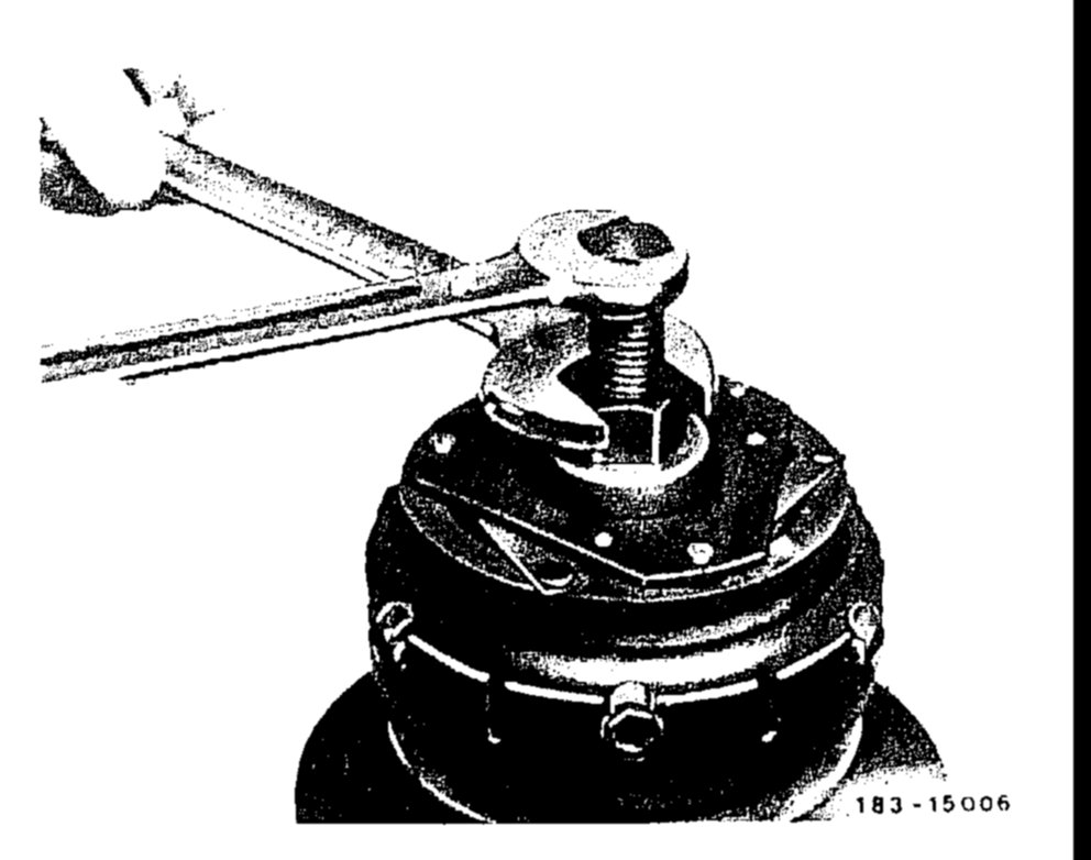
11. Hold the hexagon head of the tool and screw in the center bolt until the clearance between spring plate and clutch body is approx. 0.5-1 mm.
12. Remove assembly tool and spacer.
13. Screw new nut onto shaft (small diameter side of nut toward the end of the shaft) and tighten it. Recheck clearance.
14. Install a/c compressor.
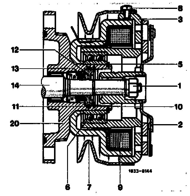
1 Nut on drive shift
2 Spring puts
3 Clutch body
5 Locking ring
6 Bearing for clutch body
7 Pulley
8 Screw with lock
9 Magnetic coil
10 Locking ring
11 0-ring
12 Slip ring
13 Shaft seal
14 Driveshaft
20 Housing cover
A/C COMPRESSOR MODEL No.627
NOTE: This a/c compressor has a modified data plate with the number 627.
1. Remove a/c compressor.
2. Attach retaining device to the a/c compressor and clamp in vice. Then seal openings with pressure test plate.
3. Remove a/c compressor from the retaining device, then clamp in again with the drive shaft pointing upward.
Assembly tool 201 589 01 35 00 can be modified for use as a combination removal and installation tool.
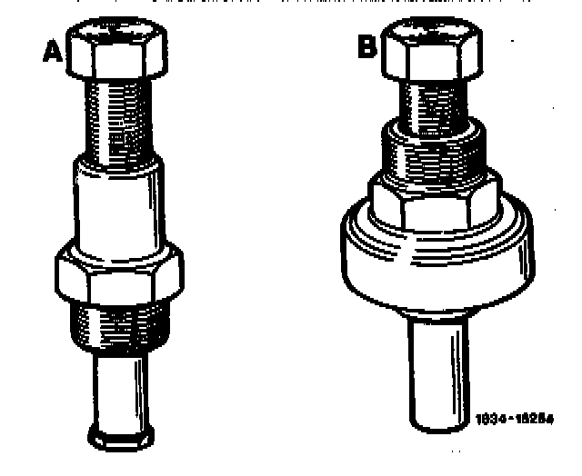
A as removal tool
B as installation tool
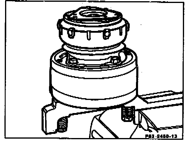
Repair Note: Measure the distance between spring plate and crankshaft before exchanging the spring plate (see illustrations). Only spring plates of the same version as the original are to be installed. For a/c compressor Model No.350 see section above.
Version on a/c compressor Model No.350
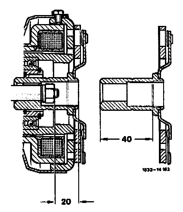
Version on a/c compressor Model No.627
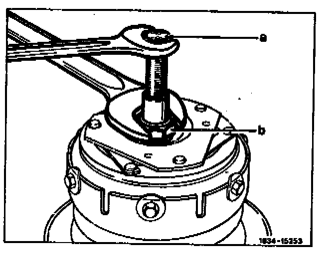
4. To remove the spring plate, unscrew the nut from the crankshaft and screw threaded sleeve (b) of the assembly tool into the spring plate.
5. Use a wrench to hold the threaded sleeve (b) in place and turn bolt (a) until the spring plate can be removed.
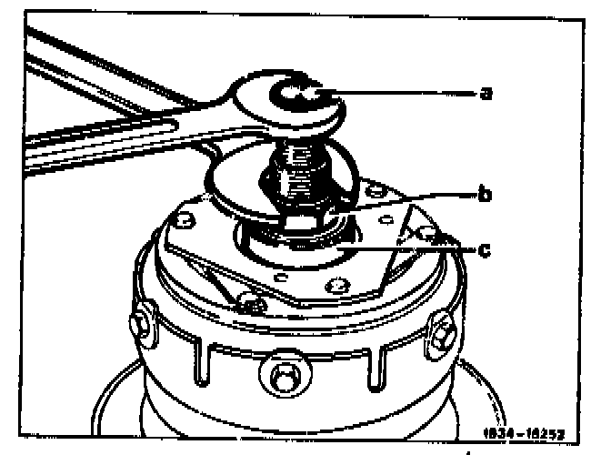
6. To install the spring plate. place bearing (c) on the spring plate. Retain belt (a) with a wrench and turn in threaded sleeve (b) until the clearance between the friction surfaces of the spring plate and the clutch body is approx. 0.5 to 1 mm.
7. Unscrew bolt (a) from the crankshaft and remove assembly tool.
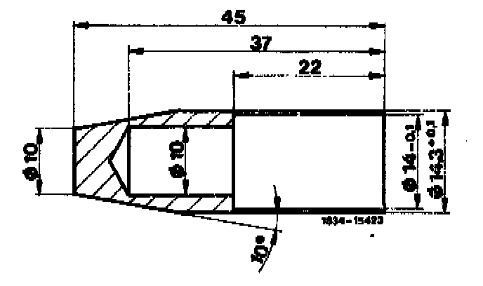
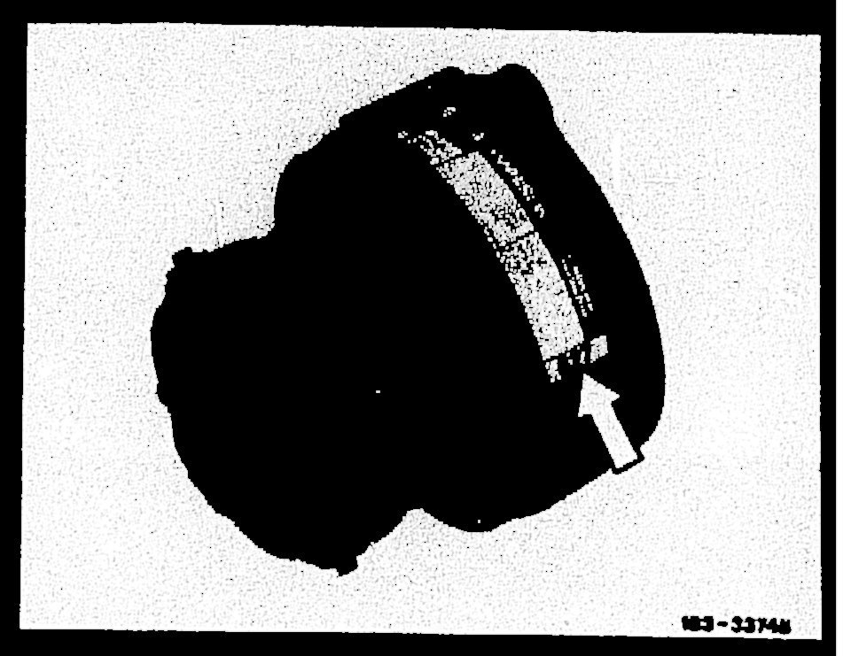
8. Replacing lip seal. A guide sleeve (illustration) must be used in order to avoid damage to the Teflon seal.
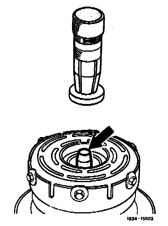
The guide sleeve is to be fabricated of C45 steel. It is then to be fitted over the end of the crankshaft before lip seal installation (illustration arrow).
NOTE: The Teflon lip seal is not to be installed in a/c compressor Model No.350.