Differential, Assembly
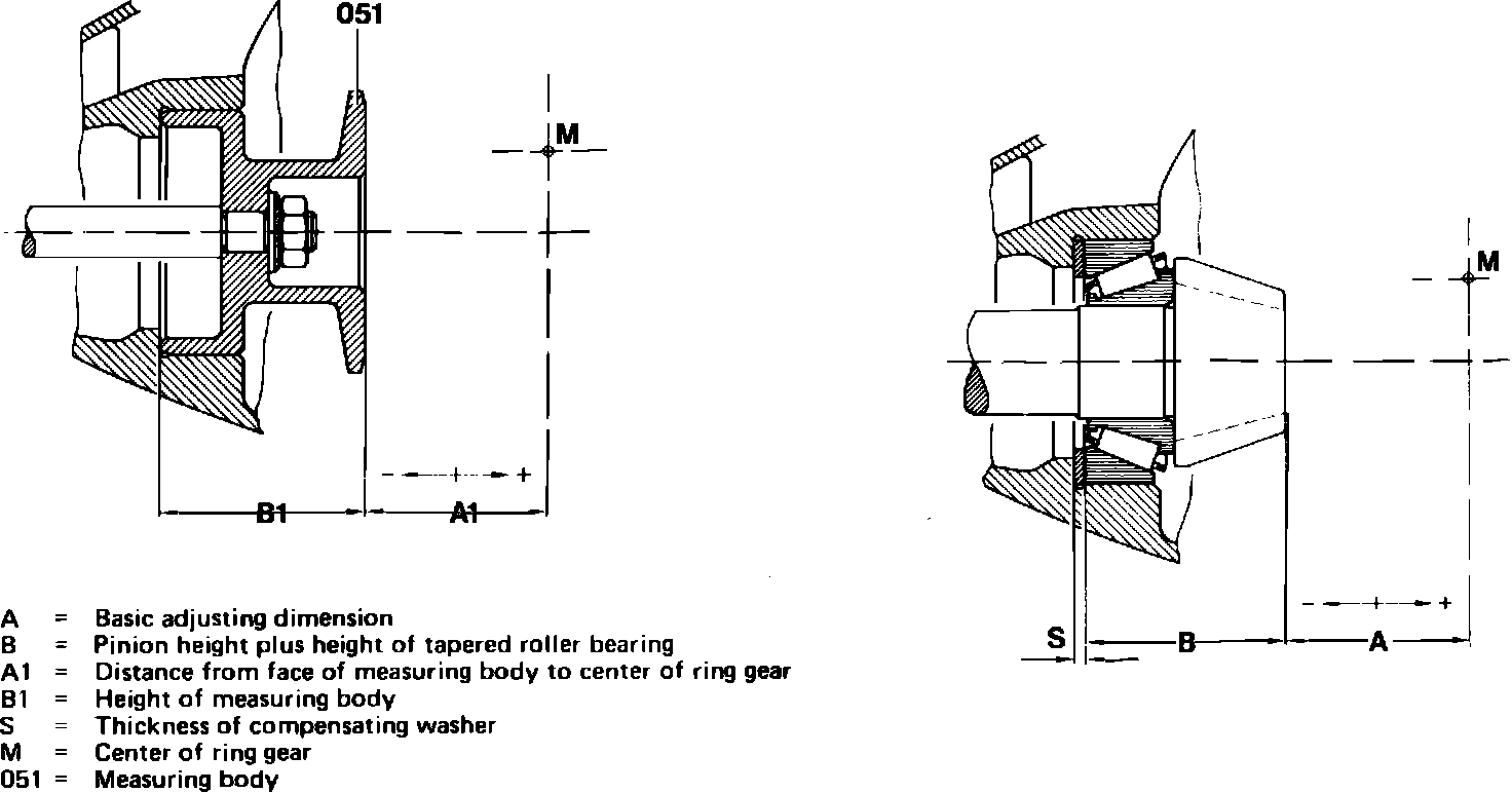
Fig. 4 Measuring pinion & measuring body height:
1. Check pinion and ring gear runout to determine compensating washer thickness ``S,'' Fig. 4. Use examples given only as a guide. Example 1, first production model differentials.
a. Determine compensating washer thickness to be used with a small center piece and a drive pinion height of 1.4 inch (37.5 mm). The difference between measuring body height ``B1'', Fig. 4 and pinion height with bearing ``B'' is .055 inch (1.4 mm). Allowable pinion deviation, which is stamped on the pinion, is + .007 inch (0.20 mm).
b. Add pinion height to allowable deviation, .055 inch (1.4 mm) + .007 inch (0.20 mm) = .062 inch (1.60 mm).
c. Difference between adjusting dimension and rear axle housing ``A1,'' Fig. 4, is +.002 inch (0.06 mm). Add amount computed in step b to the measured value of ``A1,'' .062 inch (1.60 mm) + .002 inch (0.06 mm) = .04 inch (1.66 mm).
d. Thickness of compensating washer to be installed is .064 inch (1.66 mm). Example 2, second production model differentials.
e. Determine compensating washer thickness to be used with a small center piece and a drive pinion height of 1.5 inch (39 mm). The difference between measuring body height ``B1,'' Fig. 4 and pinion height with bearing ``B'' is .062 inch (1.6 mm). Allowable pinion deviation, which is stamped on the pinion is + .077 inch (0.20 mm).
f. Add pinion height to allowable deviation, .062 inch (1.6 mm) + .007 inch (0.20 mm) = .069 inch (1.80 mm).
g. Difference between adjusting dimension and rear axle housing ``A1,'' Fig. 4, is + .002 inch (0.06 mm). Add amount computed in step f to the measured value of ``A1,'' .069 inch (1.80 mm) + .002 inch (0.06 mm) = .071 inch (1.86 mm).
h. Thickness of compensating washer to be installed is .071 inch (1.86 mm).
2. Check backlash of differential and ring gear as follows:
a. Thoroughly clean ring rear bore and differential housing seat.
Fig. 5 Measuring flange dimension ``B'':
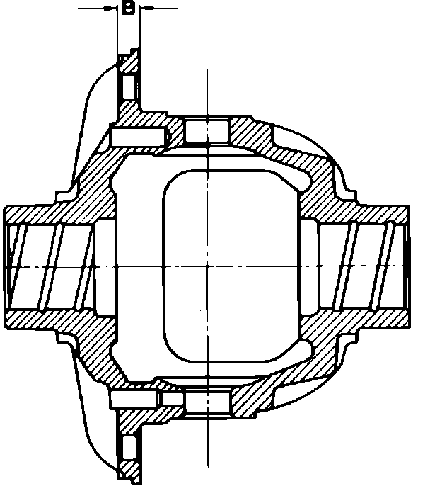
b. Using a heat lamp, heat ring gear to 140-158°F (60-70°C) and position onto differential housing. If the ring gear cannot be seated onto the differential housing, use a soft faced mallet and gently tap ring gear into place. During installation of a new differential housing, or when using new ring gear bolts. Ensure bolts are of correct length. For flange dimension ``B,'' Fig. 5, which is .314 inch (8 mm) thick, use .708 inch (18 mm) long bolts. For .393 inch (10 mm) thick flanges, use .787 inch (20 mm) long bolts only.
c. Torque ring gear bolts to 59 ft. lbs. (80 Nm) on vehicles equipped with standard differential and small center piece, 74 ft. lbs. (100 Nm) on vehicles equipped with locking differential and small center piece, or 86 ft. lbs. (120 Nm) on vehicles equipped with large center piece.
d. Vehicles equipped with small center pieces, install right hand side of differential into lateral bearing cap, until differential clears rear axle housing and is properly positioned. Vehicles equipped with large center pieces, install differential into rear axle housing.
e. Install compensating washers onto bearing cap and sealing rings into bearing cap grooves.
f. On first production model differentials only, install both bearing caps onto the rear axle housing, so the designation ``Unten'' is at the bottom. If the bearing caps bind in the rear axle housing bore, use a soft faced mallet and gently tap the caps into place.
g. Install spread gauge mounting blocks at right and left of rear axle housing mating surface. Position spread gauge with dial indicator onto mounting blocks, and set dial indicator to zero. Remove gauge.
h. Torque bearing cap bolts to 15 ft. lbs. (20 Nm), alternating directly opposite from each bolt torqued.
i. Install spread gauge onto mounting blocks and measure spread (widening) of rear axle housing. The required spread of the rear axle housing and the correct preload of the tapered roller bearings on the differential is obtained when rear axle housing spread is between .004 inch (0.10 mm) to .006 inch (0.15 mm), for small center pieces and .006 inch (0.15 mm) to .008 inch (0.20 mm), for large center pieces. If the rear axle housing spread is insufficient, incorporate thinner compensating washers into both bearing caps.
3. On standard differential units:
a. Install suitable mandrels into differential housing bores.
Fig. 6 Standard differential, disassembled view:
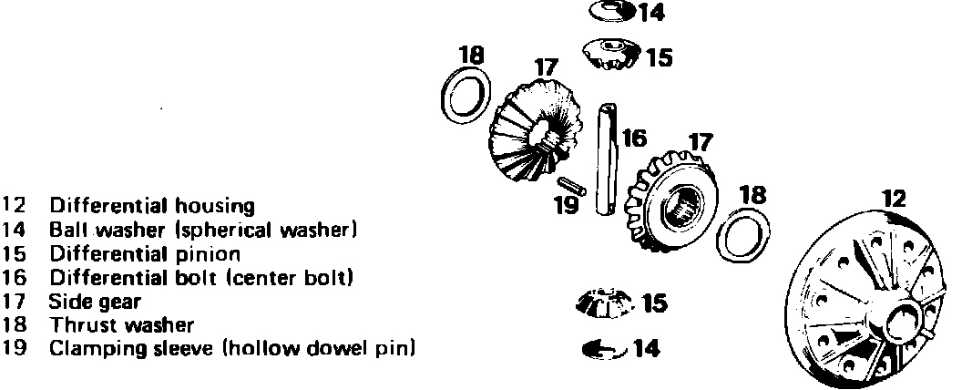
Fig. 7 Early & later production model ball washers:
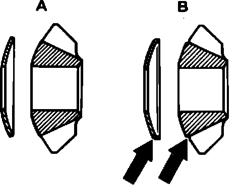
b. Install thrust washers (18), Fig. 6, onto side gears (17). Position both side gears and washers assemblies onto the mandrels and into differential housing (12). The differential ball washers of the present production model ``B,'' are provided with a collar at the outside diameter, Fig. 7, and the differential pinions with a shoulder (arrow).
c. Using the mandrels, turn both differential pinions (15) and ball washers (14) into the differential housing (12).
d. Using a suitable drift, install into differential housing to align differential pinions and ball washers.
e. Check friction torque of pinions and gears. Friction torque should be 22-66 ft. lbs. Use correct thrust washers for side gears to allow proper friction torque during assembly.
f. Using a hammer and drift, install differential bolt (16) and clamping sleeve (19) into differential housing (12).
g. Using an arbor press, install tapered roller bearings inner races onto differential housing.
Fig. 8 Positive traction differential, disassembled view:
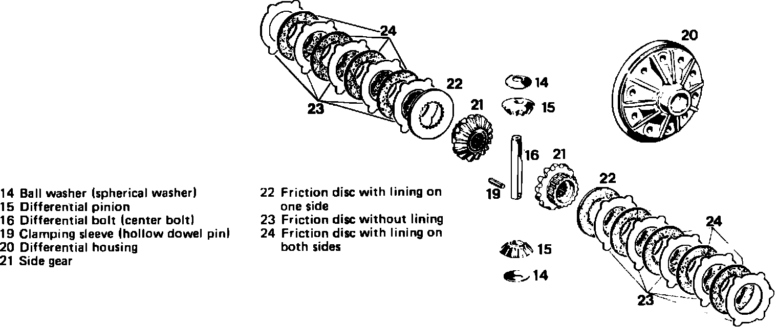
4. On positive traction differential units:
a. Lubricate friction disc Nos. (22 and 24), Fig. 8, with Hypoid gear oil or equivalent, and install in proper sequence, Fig. 8, onto both side gears (21).
Fig. 7 Early & later production model ball washers:
b. Insert left hand side gear and friction disc assembly into mandrel, and install into differential housing. Install right hand side gear with friction discs into differential housing. The differential ball washers of the present production model ``B,'' are provided with a collar at the outside diameter, Fig. 7, and the differential pinions with a shoulder (arrow).
c. Install one differential pinion and ball washer into differential and turn downward.
d. Install second differential pinion and ball washer directly opposite the first turn down until differential pinion and housing bores are in alignment.
e. Using a suitable drift, align differential pinions and ball washers.
f. Check friction torque of differential pinions and gears. Friction torque should be approximately 59-19 ft. lbs.
g. Using an arbor press, install differential bearing bolt and clamping sleeve into differential housing. Install inner races onto tapered roller bearing