B1436
Preparation For Test:
1. Review General Information, Version Coding, Diagnosis, DTC Memory, Recalling Actual Values, Component Locations, Connection of Components and Preparation for Test.
2. Voltage supply to all control modules and CAN data lines ok,
3. Unlock vehicle via Radio/IR remote central locking.
4. Fuses OK,
5. Battery voltage 11 to 14 V,
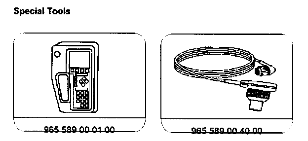
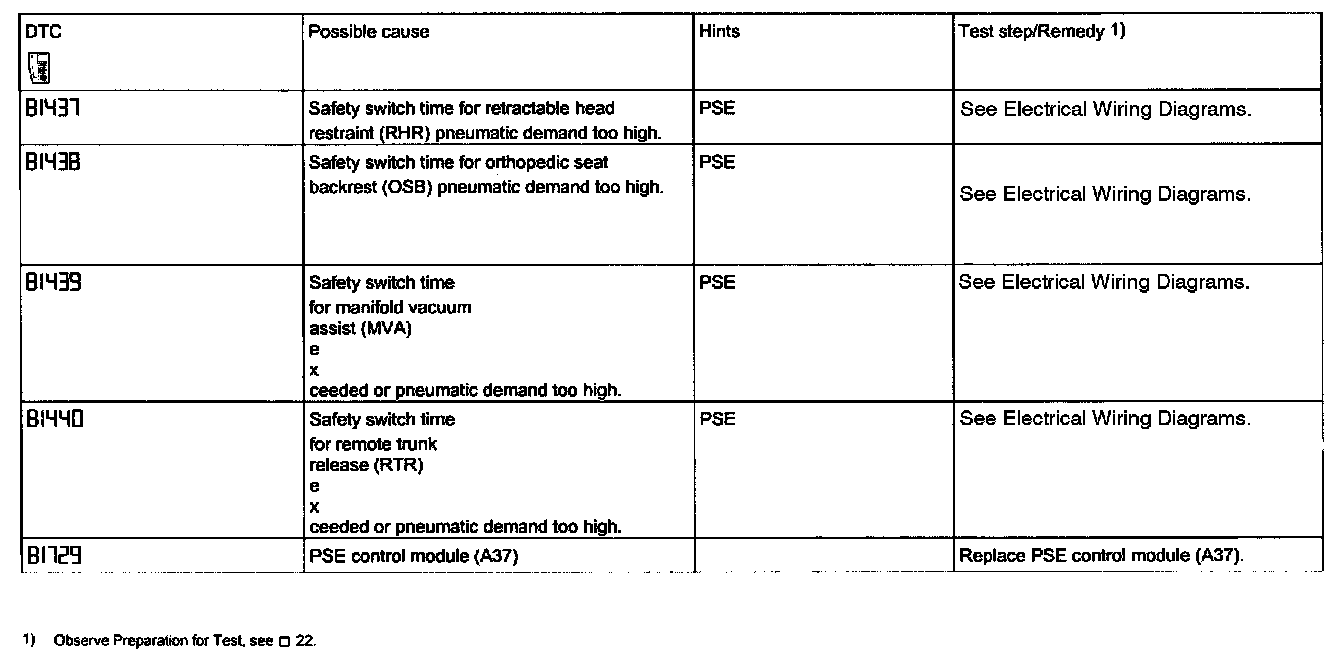
6. Connect the Hand-Held Tester (HHT) to x 11/4, according to diagram,
7. Check for additional DTC's in ATA control module.
NOTE:
- The DTC memory can only be readout and erased via the HHT. Entry into the DTC memory for DAS is via the HHT display: Functions; Locking systems; Central locking or Remote trunk release; DTC memory. When reading out the DTC's, it is possible that not all DTC's of the systems CL, OSB. MVA, RHR, RTR are located in the PSE control module (A37). DTC's not found in the PSE control module may be found in the Signal pick-up and activation module (SAM) (N1O/1) or Lower control field control module (N72).
- Readout DTC memory and note failure codes.
- Perform repairs of noted failures as per fault table.
- Interrupt PSE control module
- Power Supply for approx. 3 seconds to erase safety memory.
Since the DTC memory has been integrated into the combination control module (N10-1 or N10-3), DTC memory must be erased after replacement of the PSE control module.
> Ohm resistance too great
< Ohm resistance too low
[]+ short circuit to positive (POS)
[]- short circuit to ground (GND)
-//- open circuit
Abbreviations:
PSE: PSE control module
SAM: Signal pick-up and activation module
UBF: Lower control field control module
The above noted abbreviations are in the third column of the following DTC memory table in bold type to advise of hints (regarding in which of the control modules the DTC is stored).
Special Tools: