Removal
EngineSpecial Tool(s):

WARNING: Do not smoke or carry lighted tobacco or open flame of any type when working on or near any fuel-related components. Highly flammable mixtures are always present and may be ignited. Failure to follow these instructions may result in personal injury.
All Vehicles
1. With the vehicle in NEUTRAL, position it on a hoist.
2. Release the fuel system pressure.
3. Disconnect the battery ground cable.
4. Disable the vehicle high voltage electrical system.
5. Drain the cooling system.
6. Drain the motor electronics cooling system.
7. Remove the intake manifold.
8. Remove the engine air cleaner.
9. Remove the catalytic converter.
10. Remove the engine coolant degas bottle.
11. Remove the accessory drive belt.
12. Remove the LH front drive halfshaft.
4x4 vehicles
13. Remove the transfer case.
4x2 vehicles
14. Remove the front drive intermediate halfshaft.

15. Remove the bolts and the lateral support crossmember.
All vehicles
16. Drain the engine oil.

17. Disconnect the heater hoses from the heater core.

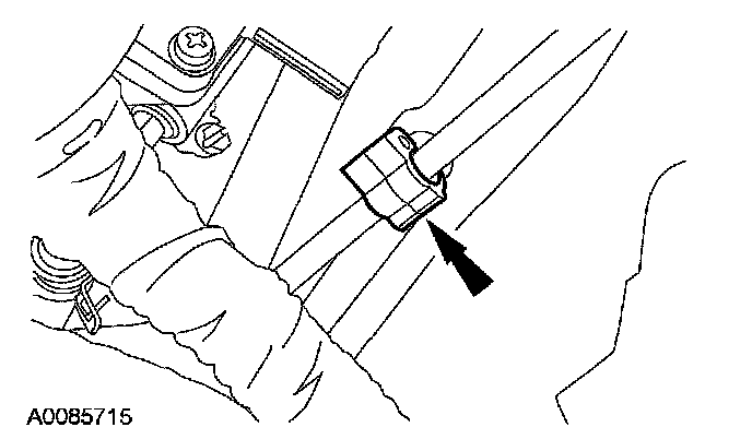
18. Detach the heater hose retaining clip from the transaxle mount stud.

19. Disconnect the upper radiator and coolant vent hoses.

20. Disconnect the following electrical connectors:
^ Secondary air injection (AIR) solenoid
^ Transaxle mount control solenoid
^ Purge valve

21. Disconnect the engine control harness.
^ Release the powertrain control module (PCM) connector.
^ Remove the harness retaining nut.

22. Disconnect the 2 engine control harness electrical connectors and the 2 pin-type retainers.

23. Remove the bolt and disconnect the transaxle harness electrical connector.

24. Disconnect the DC-to-DC converter electrical connector and pin-type retainer.

25. Disconnect and remove the fuel supply tube and evaporative emissions (EVAP) tube.

26. NOTE: Parts removed from view for clarity.
If equipped, position the block heater wiring harness aside.
^ Detach the 3 harness retainer clips.
^ Route the harness through the radiator support into the engine compartment.

27. Remove the 2 bolts and disconnect the auxiliary coolant pump electrical connector. Position the auxiliary coolant pump aside.
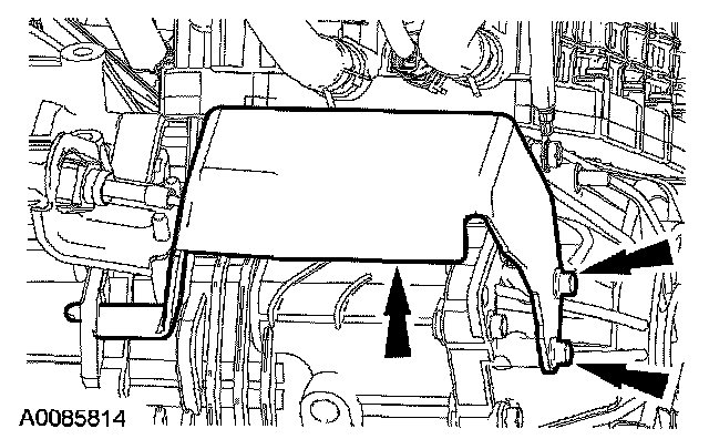
28. Remove the bolts and the transaxle control snow shield.

29. Disconnect the transaxle control cable.
^ Release the transaxle control cable from the control lever.
^ Remove the nuts from the transaxle control cable bracket.
30. Disconnect the pin-type retainer.

31. Disconnect the pin-type retainer and position the transaxle control cable aside.

32. Disconnect the transaxle coolant temperature sensor electrical connector and pin-type retainer.

33. Disconnect the transaxle coolant hoses.

34. Remove the nut and the ground cable.

35. Remove the 2 bolts and position the motor electronics coolant pump aside.

36. Disconnect the lower radiator hose from the radiator.

37. Disconnect the A/C compressor electrical connector and remove the 3 bolts. Position the A/C compressor aside and support the compressor with a length of mechanic's wire.

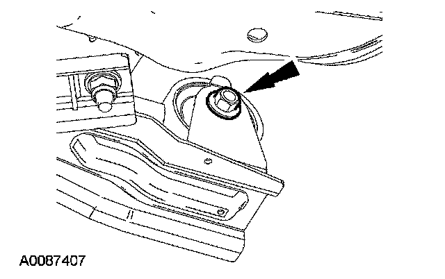
38. Remove the front roll restrictor bolt.
39. Remove the rear roll restrictor bolt.

40. Remove the nut, bolts and the engine support crossmember.

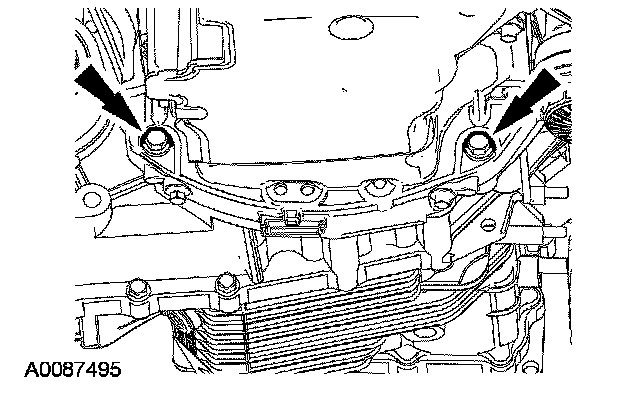
41. NOTE: The transaxle-to-engine bolts differ in length. Mark the bolts for correct installation.
Remove the 2 transaxle-to-engine bolts.
42. NOTE: The transaxle-to-engine bolts differ in length, mark the bolts for correct installation.
Remove the 2 transaxle-to-engine bolts.
43. CAUTION: Due to the weight of the transaxle, special care should be taken to mount the powertrain securely to the lift table.
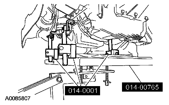
Using the special tools, secure the engine to the lift table.

44. Remove the engine mount bracket bolt.

45. Remove the nuts and the engine mount bracket.

46. Remove the RH transaxle mount bracket nut.

47. Remove the bolts and the RH transaxle mount bracket.

48. Remove the bolt, nut and the rear transaxle mount brace.

49. Remove the nuts, bolt and rear transaxle mount.
50. Lower the engine and transaxle from the vehicle.
51. Using the engine crane and spreader bar, remove the engine and transaxle from the lift table.

52. Disconnect the high voltage wiring harness electrical connector.

53. Disconnect the 2 high voltage wiring harness electrical connectors and position the harness aside.
54. NOTE: The transaxle-to-engine bolts differ in length, mark the bolts for correct installation.
Remove the remaining 6 engine-to-transaxle bolts and separate the engine and transaxle.
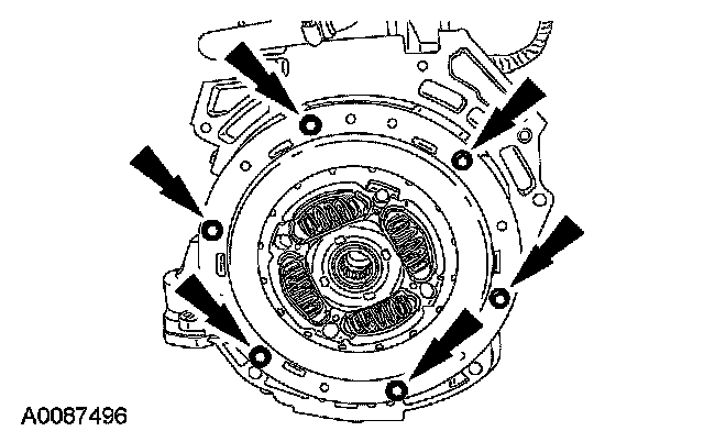
55. NOTE: Due to packaging requirements the correct bolt must be used at the damper locations.
NOTE: The damper contains a clutch which is designed to slip briefly during vehicle operation. It is essential that no grease, oil or cleaning solvents be allowed to contaminate the slip clutch. Do not use grease on transmission input shaft. Should the damper become contaminated, it must be replaced.
Remove the bolts and the transaxle damper.