Lumbar Assembly
LUMBAR ASSEMBLYSpecial Tool(s):
Special Tool(s)
Front Seat Backrest (Part 1):

Front Seat Backrest (Part 2):

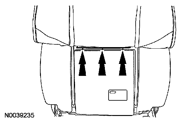
Driver Seat Cushion (Part 1):

Driver Seat Cushion (Part 2):

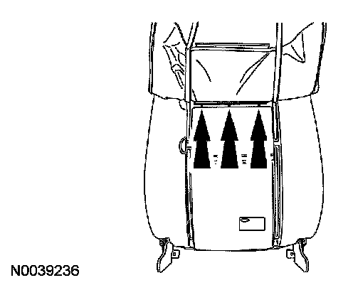
Passenger Seat Cushion (Part 1):

Passenger Seat Cushion (Part 2):

Exploded View
Removal and Installation
WARNING:
- Always wear safety glasses when repairing an air bag supplemental restraint system (SRS) vehicle and when handling an airbag module. This will reduce the risk of injury in the event of an accidental deployment.
- To reduce the risk of personal injury, do not use any memory saver devices.
NOTE:
- If a seat equipped with a supplemental restraint system (SRS) component is being serviced, the SRS must be depowered.
- The air bag warning lamp illuminates when the RCM fuse is removed and the ignition switch is ON. This is normal operation and does not indicate a supplemental restraint system (SRS) fault.
- The SRS must be fully operational and free of faults before releasing the vehicle to the customer.
All seats
1. Remove the front seat and depower the supplemental restraint system (SRS).
2. Remove the front seat backrest.
3. Remove the plastic rivets attaching the backrest trim cover to the inboard and outboard recliners.
4. CAUTION: Use care when separating the seat back trim cover from the hook-and-loop strip, or the hook-and-loop strip can be torn from the backrest foam pad.
Release the backrest trim cover lower J-clip, hook-and-loop strips and invert the trim cover to the first row of hog rings.
Seats with manual lumbar
5. Release the 2 manual lumbar spring clips from the backrest frame and remove the manual lumbar.
- Route out the manual lumbar cable.
Seats with power lumbar
6. Remove the first row of hog rings.
7. Release the hook-and-loop strips, invert the trim cover and remove the second row of hog rings.
8. Remove the power lumbar adjust assembly.
1. Disconnect the power lumbar adjust assembly motor electrical connector.
2. Release the 2 power lumbar adjust assembly lower pin-type retainers to the backrest frame.
3. Slide the power lumbar adjust assembly rods out of the backrest frame at the top and remove the power lumbar adjust assembly.
All seats
9. To install, reverse the removal procedure.
10. Install the front seat backrest.
11. Install the front seat and repower the SRS. If a passenger seat has been serviced, do not prove out the SRS at this time.
Passenger seat
12. Carry out the Occupant Classification Sensor (OCS) System Zero Seat Weight Test and prove out the SRS.