Intermittent Diagnostic Techniques
Intermittent Diagnostic Techniques
Intermittent diagnostic techniques help find and isolate the root cause of intermittent concerns associated with the electronic engine control (EEC) system. The information is organized to help find the concern and carry out the repair. The process of finding and isolating an intermittent concern starts with recreating a fault symptom, accumulating powertrain control module (PCM) data, and comparing that data to typical values, then analyzing the results. Refer to the scan tool manufacturer's instruction manual for the functions described below.
Before proceeding, be sure that:
- Customary mechanical system tests and inspections do not reveal a concern. NOTE: Mechanical component conditions can make a PCM system react abnormally.
- Technical Service Bulletins (TSBs) and On-line Automotive Service Information System (OASIS) messages, if available, are reviewed.
- Quick Test and associated diagnostic subroutines have been completed without finding a concern, and the symptom is still present.
Recreating the Fault
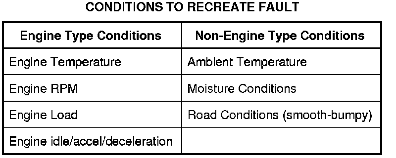
Recreating the concern is the first step in isolating the cause of the intermittent symptom. A thorough investigation should start with the customer information worksheet located in the back of this manual. If freeze frame data is available, it may help in recreating the conditions at the time of a malfunction indicator lamp diagnostic trouble code (MIL DTC). Listed below are some of the conditions for recreating the concern:
Conditions To Recreate Fault:
Accumulating PCM Data
PCM data can be accumulated in a number of ways. This includes circuit measurements with a digital multimeter (DMM) or scan tool parameter identification (PID) data. Acquisition of PCM PID data using a scan tool is one of the easiest ways to gather information. Gather as much data as possible when the concern is occurring to prevent improper diagnosis. Data should be accumulated during different operating conditions and based on the customer description of the intermittent concern. Compare this data with the known good data values located in Typical Diagnostic Reference Values Typical Diagnostic Reference Values. This requires recording data in 4 conditions for comparison: 1) KOEO, 2) Hot Idle, 3) 48 km/h (30 mph), and 4) 89 km/h (55 mph).
Comparing PCM Data
After the PCM values are acquired, it is necessary to determine the concern area. This typically requires the comparison of the actual values from the vehicle to the typical values from the Typical Diagnostic Reference Values Typical Diagnostic Reference Values. The charts apply to different vehicle applications (engine, model, transmission).
Analyzing PCM Data
Look for abnormal events or values that are clearly incorrect. Inspect the signals for abrupt or unexpected changes. For example, during a steady cruise most of the sensor values should be relatively stable. Sensors such as throttle position (TP), mass air flow (MAF), and RPM that change abruptly when the vehicle is traveling at a constant speed are clues to a possible concern area.
Look for an agreement in related signals. For example, if the APP1, APP2, or APP3, is changed during acceleration, a corresponding change should occur in idle air control (IAC), RPM, and SPARK ADV PID.
Make sure the signals act in proper sequence. An increase in RPM after the TP1 and TP2 is increased is expected. However, if the RPM increases without a TP1 and TP2 change, a concern may exist.
Scroll through the PID data while analyzing the information. Look for sudden drops or spikes in the values.