Inspection Procedure 1
INSPECTION PROCEDURE 1: Communication between Scan Tool and the TCL/ASC-ECU is not possible.Data Link Connector Circuit (Part 1):
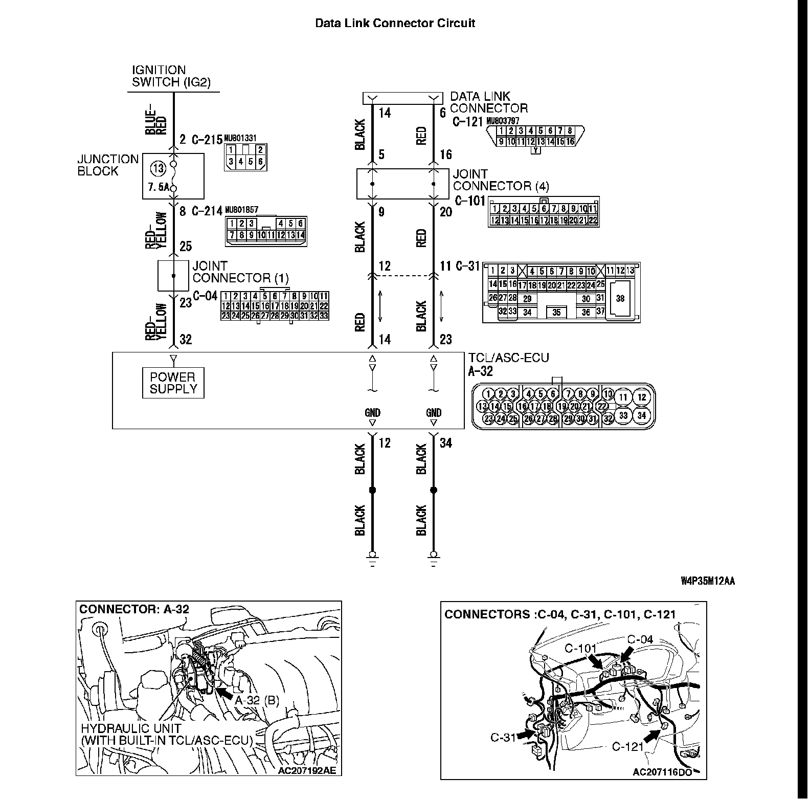
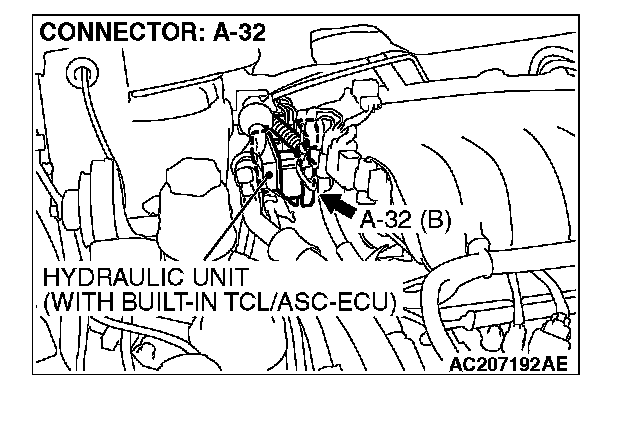
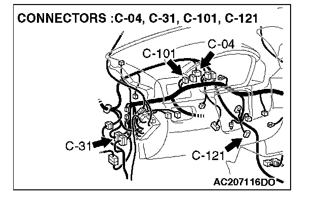
Data Link Connector Circuit (Part 2):
TECHNICAL DESCRIPTION (COMMENT)
If the scan tool (M.U.T.-III Sub Assembly) can not communicate with the ABS system, the CAN bus lines may be defective. If the ABS system does not work, the TCL/ASC-ECU or its power supply circuit may be defective.
TROUBLESHOOTING HINTS (The most likely causes for this case:)
^ Damaged wiring harness or connector
^ Malfunction of the hydraulic unit (Integrated with TCL/ASC-ECU)
DIAGNOSIS
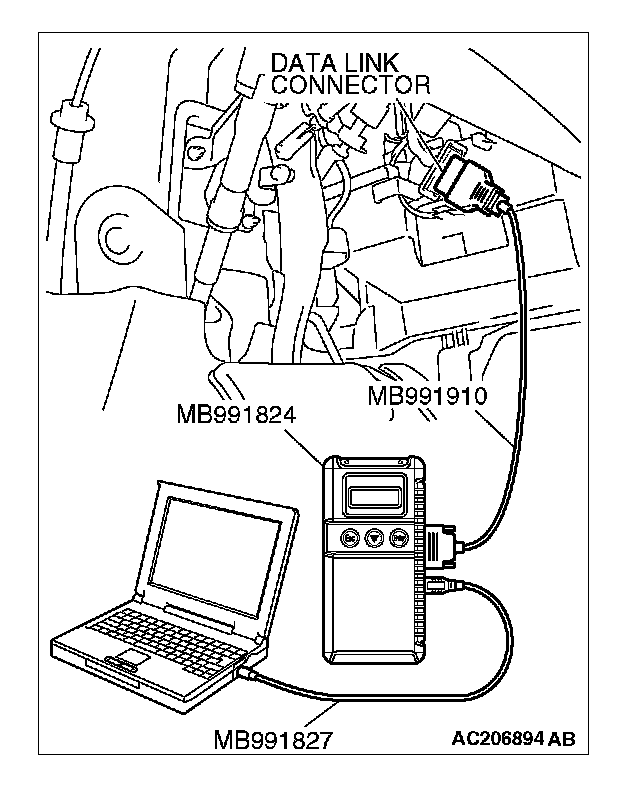
Required Special Tools:
^ MB991958: Scan Tool (M.U.T.-III Sub Assembly)
- MB991824: Vehicle Communication Interface (V.C.I.)
- MB991827: M.U.T.-III USB Cable
- MB991910: M.U.T.-III Main Harness A
STEP 1. Using scan tool MB991958, diagnose the CAN bus line.
CAUTION: To prevent damage to scan tool MB991958, always turn the ignition switch to the "LOCK" (OFF) position before connecting or disconnecting scan tool MB991958.
Use scan tool MB991958 to diagnose the CAN bus lines.
(1) Connect scan tool MB991958 to the data link connector.
(2) Turn the ignition switch to the "ON" position.
(3) Diagnose the CAN bus line.
Q: Is the check result satisfactory?
YES: Check and repair the power supply circuit system. Inspection Procedure 2
NO: Repair the CAN bus lines.