Inspection Procedure 5
Hunting (Repeated Acceleration and Deceleration) Occurs at the Set Vehicle Speed.COMMENT
The output shaft speed sensor signal or the throttle body is suspected.
TROUBLESHOOTING HINTS (THE MOST LIKELY CAUSES FOR THIS CASE:)
- Malfunction of the output shaft speed sensor.
- Malfunction of the throttle body.
- Malfunction of the PCM.
DIAGNOSIS
Required Special Tools:
- MB991958: Scan Tool (MUT-III Sub Assembly)
- MB991824: V.C.I.
- MB991827: MUT-III USB Cable
- MB991910: MUT-III Main Harness A
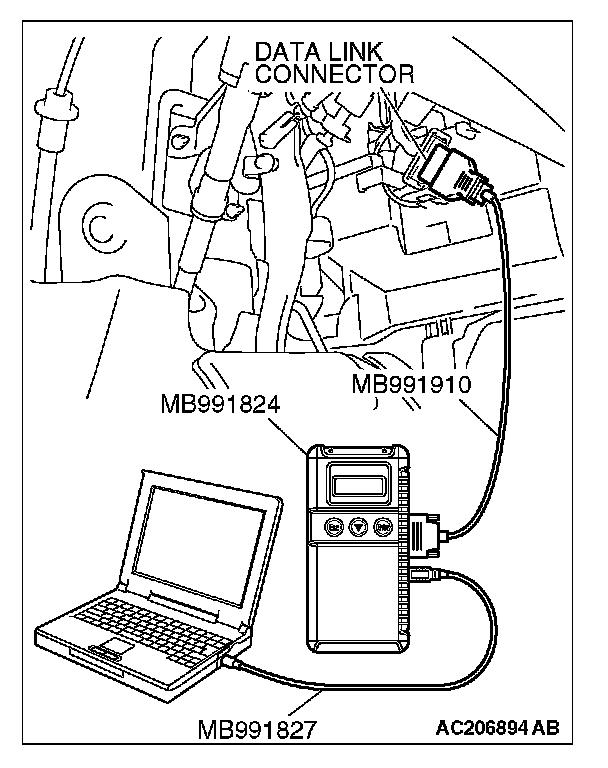
STEP 1. Using scan tool MB991958, read the diagnostic trouble code.
CAUTION: To prevent damage to scan tool MB991958, always turn the ignition switch to the "LOCK" (OFF) position before connecting or disconnecting scan tool MB991958.
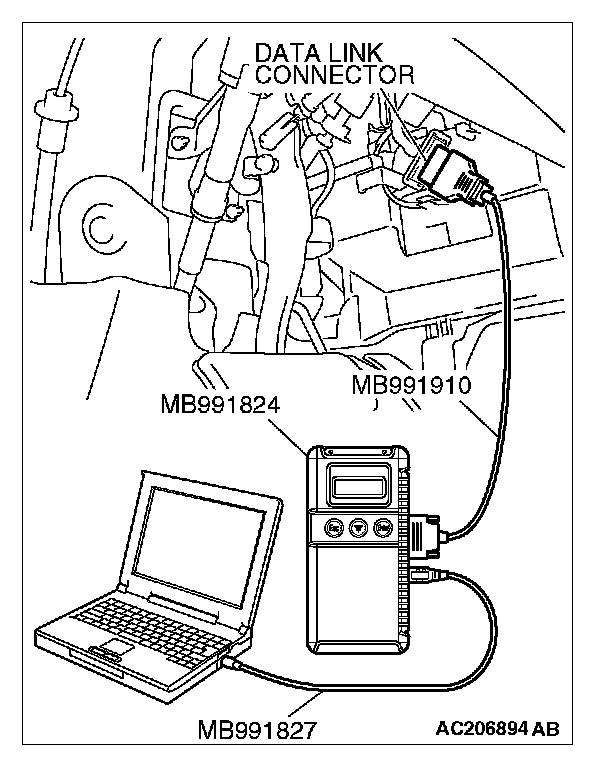
1. Connect scan tool MB991958 to the data link connector.
2. Turn the ignition switch to the "ON" position.
3. Check for A/T system diagnostic trouble code. (Refer to A/T Diagnosis - Diagnostic Function - How to Read and Erase Diagnostic Trouble Code).
4. Turn the ignition switch to the "LOCK" (OFF) position.
5. Disconnect scan tool MB991958.
Q: Is any DTC set?
YES: Diagnose the A/T system. (Refer to A/T Diagnosis - Diagnostic Trouble Code Chart). Diagnostic Trouble Code Descriptions Then go to Step 4.
NO: Go to Step 2.
STEP 2. Using scan tool MB991958, read the diagnostic trouble code.
CAUTION: To prevent damage to scan tool MB991958, always turn the ignition switch to the "LOCK" (OFF) position before connecting or disconnecting scan tool MB991958.
1. Connect scan tool MB991958 to the data link connector.
2. Turn the ignition switch to the "ON" position.
3. Check for MFI system diagnostic trouble code. (Refer to MFI Diagnosis - Diagnostic Function - How to Read and Erase Diagnostic Trouble Code). Reading Diagnostic Trouble Codes
4. Turn the ignition switch to the "LOCK" (OFF) position.
5. Disconnect scan tool MB991958.
Q: Is any DTC set?
YES: Diagnose the MFI control system. (Refer to MFI Diagnosis - Diagnostic Trouble Code Chart). Diagnostic Trouble Code Descriptions Then go to Step 4.
NO: Go to Step 3.
STEP 3. Retest the system
Q: Does hunting occur?
YES: Replace the PCM [Refer to Power Control Module (PCM)]. Then go to Step 4.
NO: It can be assumed that this malfunction is intermittent (Refer to How to Use Troubleshooting/Inspection Service Points - How to Cope with Intermittent Malfunction).
STEP 4. Retest the system
Q: Does a hunting occur?
YES: Return to Step 1.
NO: The procedure is complete.