Heater
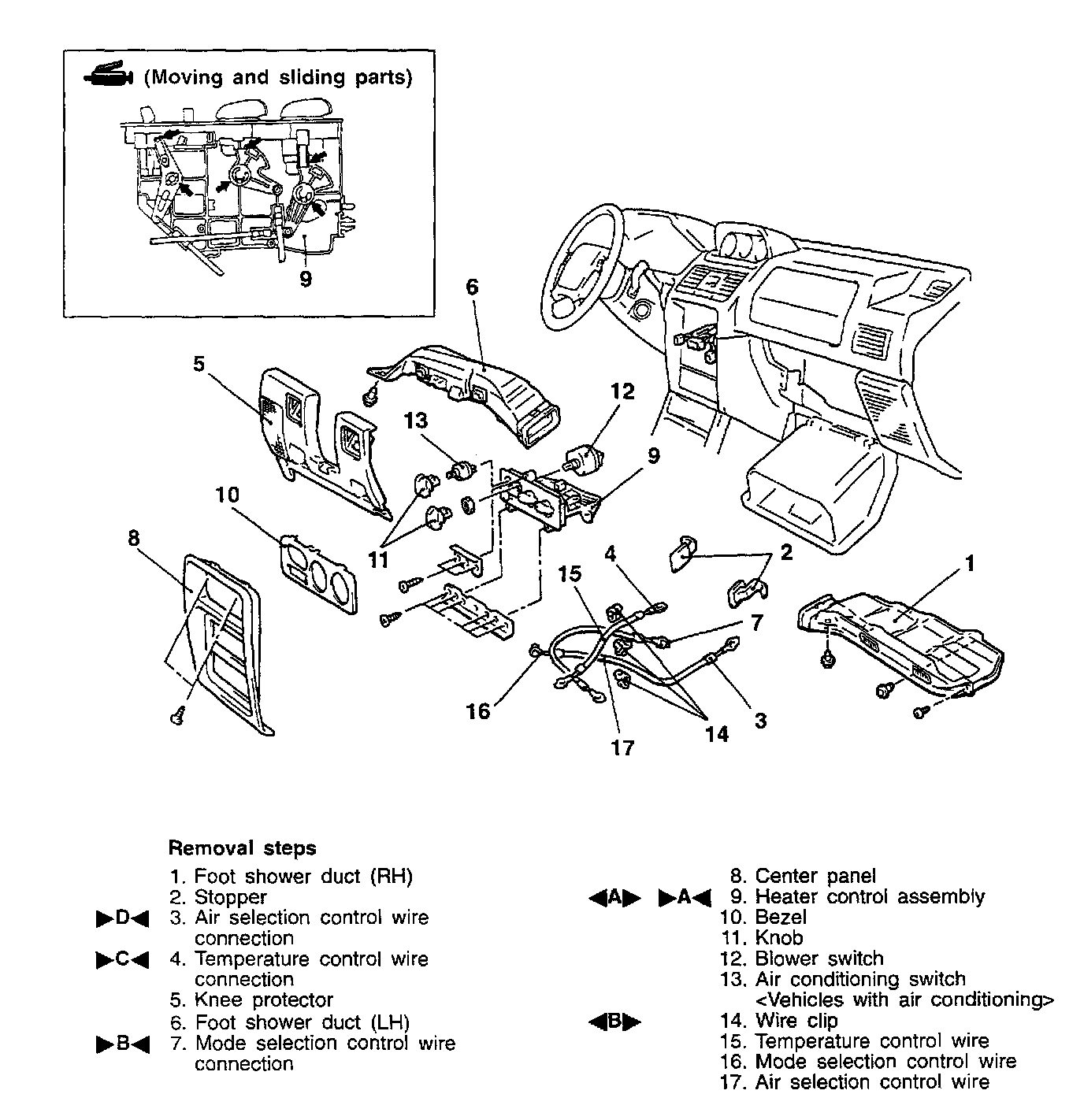
REMOVAL SERVICE POINTS
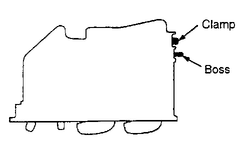
A HEATER CONTROL ASSEMBLY REMOVAL
Snap the boss and clamp with cutters or a flat-tipped screwdriver, etc to remove the heater control assembly.
NOTE: The boss and clamp are needed for assembly line at the factory, but not needed for service work.
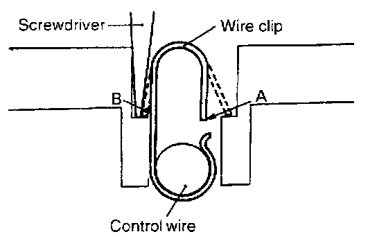
B WIRE CLIP REMOVAL
Remove the wire clip by inserting a screwdriver in the position shown in the illustration and pushing the wire clip in directions A and B.
INSTALLATION SERVICE POINTS
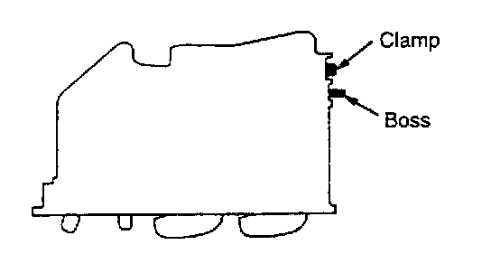
A HEATER CONTROL ASSEMBLY INSTALLATION
Always snap the boss and clamp before installing a new heater control assembly to the instrument panel.
NOTE: The boss and clamp are needed for assembly line at the factory, but not needed for service work.
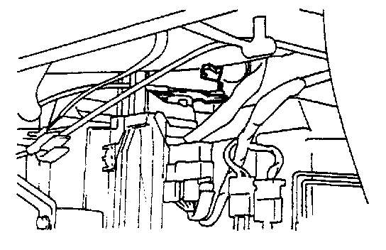
B MODE SELECTION CONTROL WIRE (HEATER UNIT SIDE) INSTALLATION
Connect the mode selection control wire to the mode selection damper lever by following the steps.
1. Move the mode selection lever to the defroster position.
2. With the air selection damper lever pressed inward in the direction indicated by the arrow, connect the inner cable of the mode selection control wire to the end of the mode selection lever, and then use a clip to secure the outer cable.
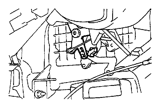
C TEMPERATURE CONTROL WIRE (HEATER UNIT SIDE) INSTALLATION
Connect the temperature control wire to the blend air damper lever by following the steps.
1. Move the temperature control lever to the far right position (HOT position).
2. With the blend air damper lever pressed completely downward in the direction indicated by the arrow, connect the inner cable of the temperature control wire to the end of the blend air damper lever, and then use a clip to secure the outer cable.
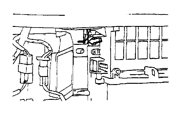
D AIR SELECTION CONTROL WIRE (BLOWER CASE SIDE) INSTALLATION
Connect the air selection control wire to the air selection damper lever by following the steps.
1. Move the air selection control lever to the recirculation position.
2. With the air selection damper lever pressed inward in the direction indicated by the arrow, connect the inner cable of the air selection lever, and then use a clip to secure the outer cable.