How to Follow Test Groups In Trouble Diagnosis
How to Follow Trouble DiagnosisDESCRIPTION
NOTE: Trouble diagnosis indicates work procedures required to diagnose problems effectively. Observe the following instructions before diagnosing.
1. Before performing trouble diagnosis, read the "Preliminary Check", the "Symptom Chart" or the "Work Flow".
2. After repairs, re-check that the problem has been completely eliminated.
3. Refer to Component Parts and Harness Connector Location for the Systems described for identification/location of components and harness connectors.
4. Refer to the Circuit Diagram for quick pinpoint check.
If you need to check circuit continuity between harness connectors in more detail, such as when a sub-harness is used, refer to Wiring Diagram in each individual section and Harness Layout in Power and Ground Distribution for identification of harness connectors.
5. When checking circuit continuity, ignition switch should be OFF.
6. Before checking voltage at connectors, check battery voltage.
7. After accomplishing the Diagnostic Procedures and Electrical Components Inspection, make sure that all harness connectors are reconnected as they were.
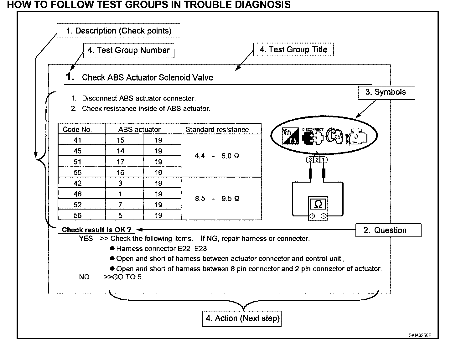
HOW TO FOLLOW TEST GROUPS IN TROUBLE DIAGNOSIS
1. Work and diagnostic procedure
Start to diagnose a problem using procedures indicated in enclosed test groups.
2. Questions and required results
Questions and required results are indicated in bold type in test group.
The meaning of are as follows:
a. Battery voltage - > 11 - 14 V or approximately 12 V
b. Voltage : Approximately 0 V - > Less than 1 V
3. Symbol used in illustration
Symbols included in illustrations refer to measurements or procedures. Before diagnosing a problem, familiarize yourself with each symbol. Refer to "Connector Symbols" and "KEY TO SYMBOLS SIGNIFYING MEASUREMENTS OR PROCEDURES".
4. Action items
Next action for each test group is indicated based on result of each question. Test group number is shown in the left upper portion of each test group.
HARNESS WIRE COLOR AND CONNECTOR NUMBER INDICATION
There are two types of harness wire color and connector number indication.
Type 1: Harness Wire Color And Connector Number Are Shown In Illustration
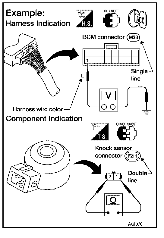
- Letter designations next to test meter probe indicate harness wire color.
- Connector numbers in a single circle (e.g. M33) indicate harness connectors.
- Connector numbers in a double circle indicate component connectors.
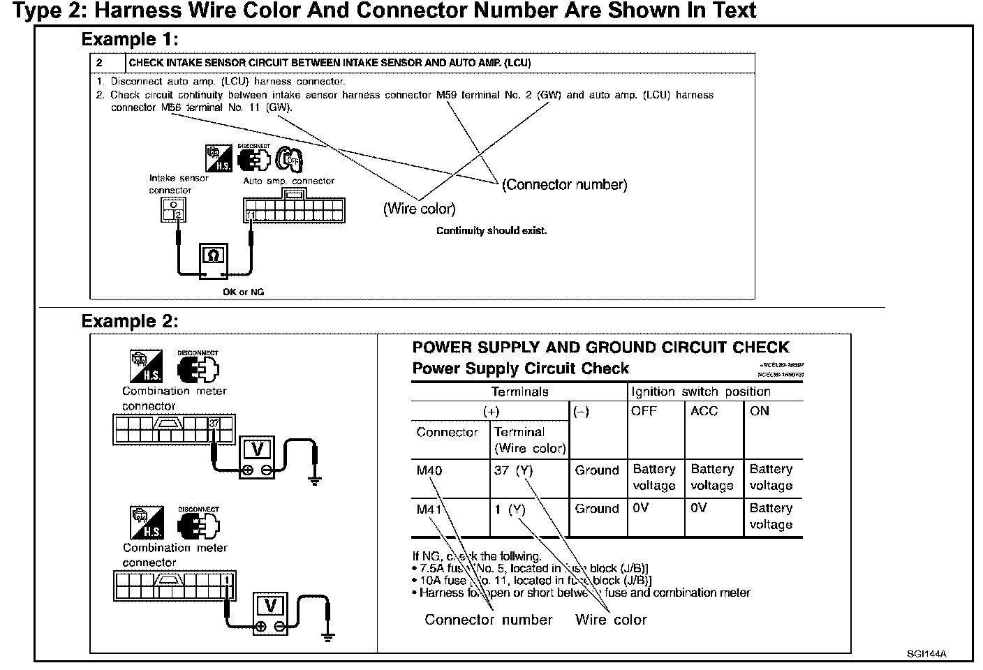
Type 2: Harness Wire Color And Connector Number Are Shown In Text
Key To Symbols Signifying Measurements Or Procedures Part 1:
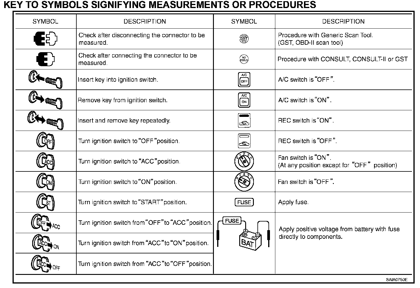
Key To Symbols Signifying Measurements Or Procedures Part 2:
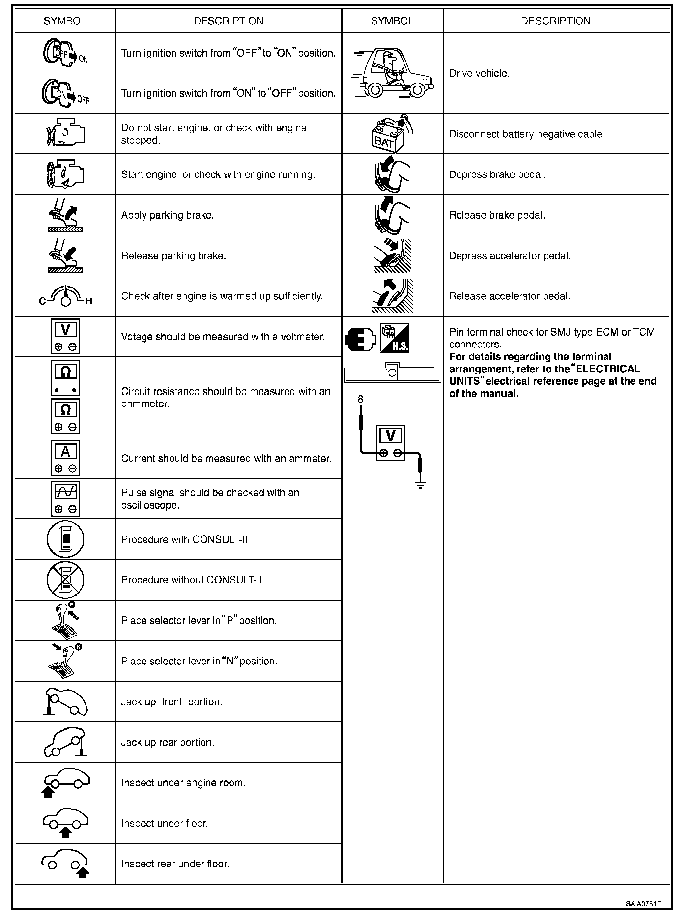
KEY TO SYMBOLS SIGNIFYING MEASUREMENTS OR PROCEDURES