Charge Pulse Signal Circuit
CHARGE PULSE SIGNAL CIRCUIT
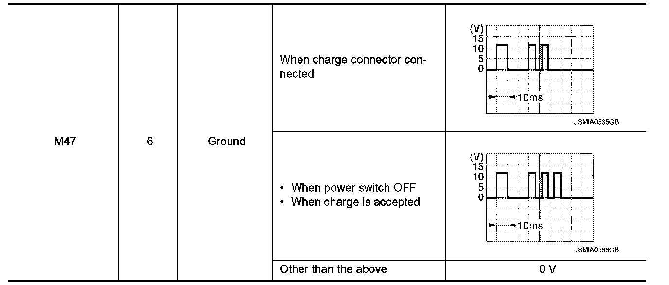
Description
The VCM outputs the charge pulse signal to the VSP control unit.
Component Function Check
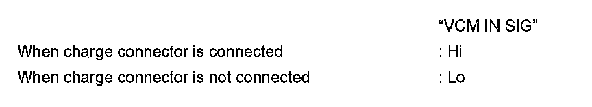
1. CHECK CHARGE PULSE INPUT SIGNAL
1.Connect the CONSULT.
2.Select the "DATA MONITOR" for the "VSP" and check the "VCM IN SIG" monitor value.
- INSPECTION END
Diagnosis Procedure
1. CHECK CHARGE PULSE SIGNAL CIRCUIT
1.Power switch OFF.
2.Disconnect VSP control unit connector and VCM connector.
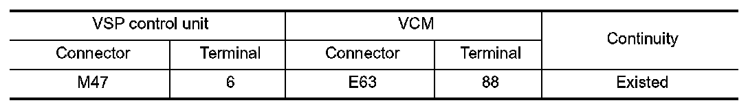
3.Check continuity between VSP control unit harness connector and VCM harness connector.
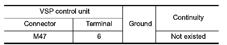
4.Check continuity between VSP control unit harness connector and ground.
Is the inspection result normal?
YES- GO TO 2.
NO- Repair the harnesses or connector.
2. CHECK CHARGE PULSE INPUT SIGNAL
1.Connect VSP control unit and stop lamp switch connector.
2.Power switch ON.
3.Check voltage between VSP control unit harness connector and ground.
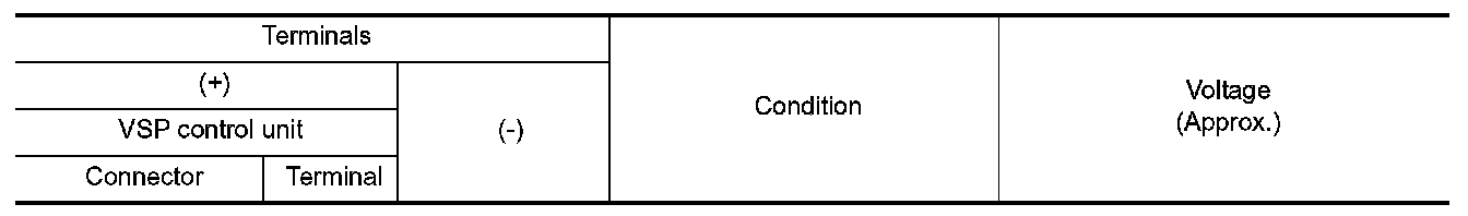
Is the inspection result normal?
YES- Replace the VSP control unit. Refer to "Removal and Installation" Approaching Vehicle Sound For Pedestrians (VSP) Control Unit.
NO- Perform "Self Diagnosis Result" of VCM.