POWER SWITCH SIGNAL CIRCUIT
POWER SWITCH SIGNAL CIRCUIT
Description
The power switch outputs the power switch signal to the VSP control unit.
Component Function Check
1. CHECK POWER SWITCH INPUT SIGNAL
1.Connect the CONSULT.
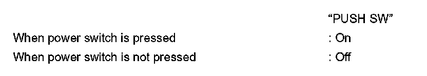
2.Select the "DATA MONITOR" for the "VSP" and check the "PUSH SW" monitor value.
- INSPECTION END
Diagnosis Procedure
1. CHECK POWER SWITCH SIGNAL CIRCUIT
1.Power switch OFF.
2.Disconnect VSP control unit and power switch connector.
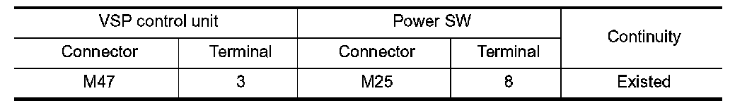
3.Check continuity between VSP control unit harness connector and power switch harness connector.
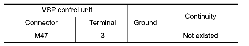
4.Check continuity between VSP control unit harness connector and ground.
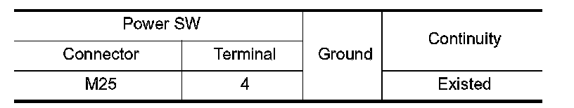
5.Check continuity between power switch harness connector and ground.
Is the inspection result normal?
YES- GO TO 2.
NO- Repair harness or connector.
2. CHECK POWER SWITCH INPUT SIGNAL
1.Connect VSP control unit and power switch connector.
2.Power switch ON.
3.Check voltage between VSP control unit harness connector and ground.
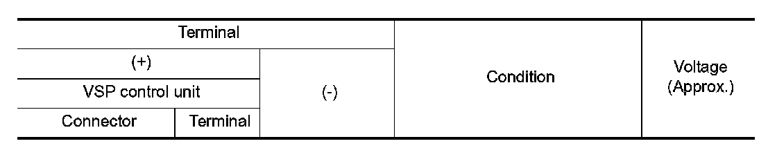
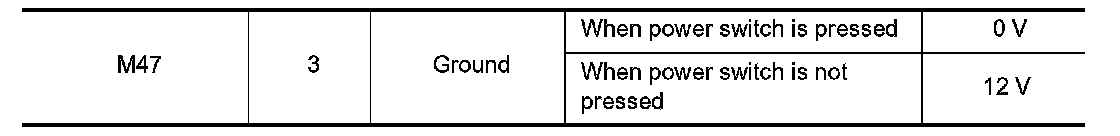
Is the inspection result normal?
YES- Replace VSP control unit. Refer to "Removal and Installation" Removal And Installation.
NO- Refer to "Component Inspection" .
Component Inspection
1. CHECK POWER SWITCH
1.Power switch OFF.
2.Disconnect power switch connector.
3.Check continuity between following terminals of the power switch.
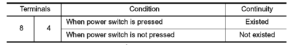
Is the inspection result normal?
YES- INSPECTION END
NO- Replace power switch.