Lower Steering Shaft Assembly Sphere Joint Preload Spring


^ Tools Required:
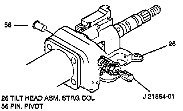
- J 21854-01 Pivot Pin Remover
- J 41352 Modular Column Holding Fixture
- Or Equivalents
REMOVAL
Remove or disconnect the following:
CAUTION: Once steering column is removed from vehicle, the column is extremely susceptible to damage.
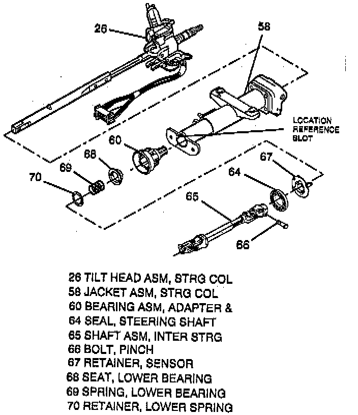
1. Steering column guide assemblies (53) and (54) from steering column jacket assembly (58).
2. Do Removal steps 1 through 8, LOWER SHROUD, UPPER SHROUD.
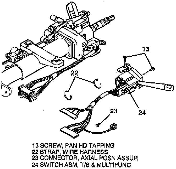
3. Two pan head tapping screws (13).
4. Turn signal & multifunction switch assembly (24).
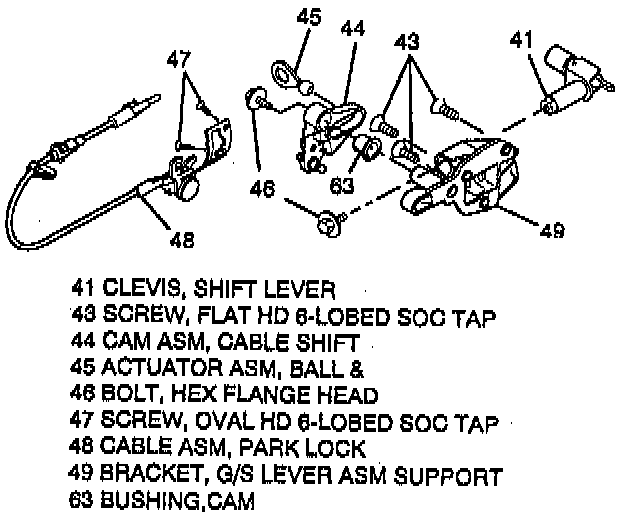
5. Linear shift assembly (40).
^ Do Removal steps 2 through 6, LINEAR SHIFT ASM (REMOVAL).
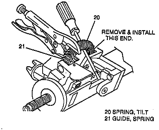
6. Refer to WARNING and do Removal steps 5 and 6, TILT SPRING.
7. Inter steering shaft assembly (65) from shaft assembly (37).
^ Remove pinch bolt (66).
8. Strg shaft seal (64) from adapter & bearing assembly (60).
9. Sensor retainer (67) from adapter & bearing assembly (60)
10. Lower spring retainer (70).
11. Lower bearing spring (69).
12. Lower bearing seat (68).
13. Adapter & bearing assembly (60) from jacket assembly (58).
14. Two pivot pins (56) using the Pivot Pin Remover.
15. Steering column tilt head assembly (26) with steering shaft assembly.
^ Install and pull tilt arm to disengage steering wheel lock shoes from dowel pins in steering column support assembly (57).
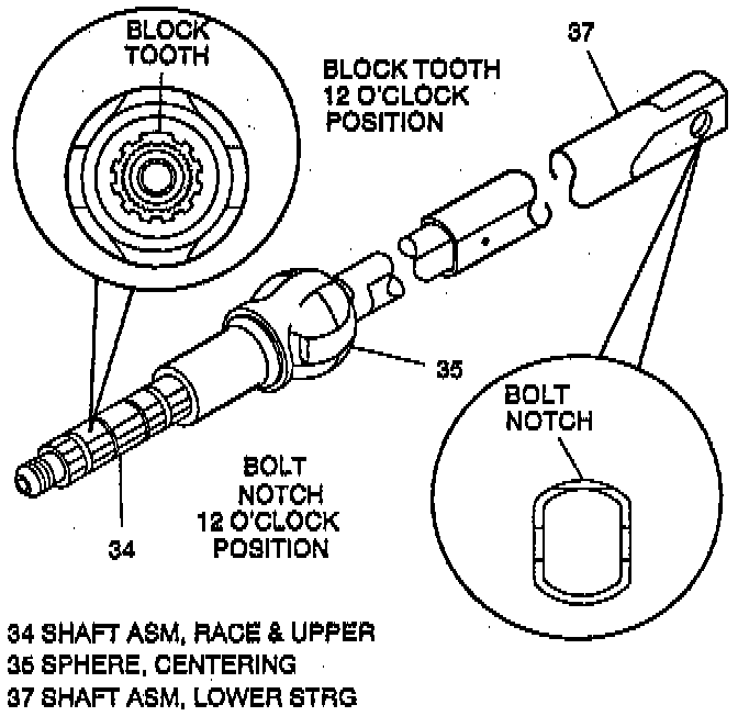
NOTE: Mark race & upper shaft assembly (34) and lower steering shaft assembly (37) to ensure proper assembly. Failure to assemble properly will cause steering wheel to be turned 180°.
DISASSEMBLE
Disassemble the following:
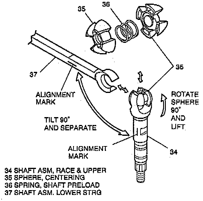
^ Lower steering shaft assembly (37) from race & upper shaft assembly (34) and steering column tilt head assembly (26).
A. Race & upper shaft assembly (34) from lower steering shaft assembly (37).
^ Tilt 90 degrees to each other and disengage.
B. Centering sphere (35) from upper shaft assembly (34).
^ Rotate sphere 90° and slip out.
C. Shaft preload spring (36) from centering sphere (35).
ASSEMBLE
Assemble the following:
^ Lower steering shaft assembly (37) to race & upper shaft assembly (34) and steering column tilt head assembly (26).
A. Shaft preload spring (36) to centering sphere (35).
B. Centering sphere (35).
^ Lubricate with lithium grease. Slip into upper shaft assembly (34) and rotate sphere 90 degrees.
C. Lower steering shaft assembly (37) to race & upper shaft assembly (34).
^ Line up marks and tilt assemblies 90 degrees to each other.
16. Four torx head screws (55).
17. Steering column support assembly (57).
INSTALLATION
Install or connect the following:
1. Steering column support assembly (57).
2. Four torx head screws (55).
^ Tighten screws (55) to 9 Nm (80 lb in).
3. Do Installation steps 1 through 4, 6, and 7, STRG COL TILT HEAD ASM.
4. Adapter & bearing assembly (60) to steering column jacket assembly (58).
^ Position tab on adapter & bearing assembly (60) with slot in steering column jacket assembly (58) and push together.
5. Lower bearing seat (68) to steering shaft assembly (37).
^ Make sure lower bearing seat (68) is in contact with adapter & bearing assembly (60).
6. Lower bearing spring (69) to steering shaft assembly (37).
7. Lower spring retainer (70) to steering shaft assembly (37).
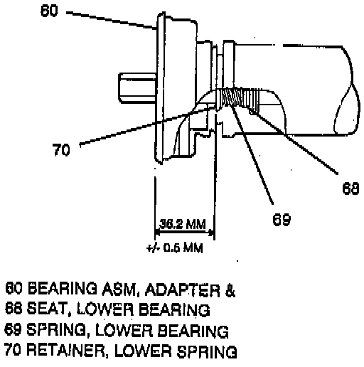
^ Press spring retainer (70) onto the steering shaft assembly (37) to 35.7 mm To 36.7 mm from end of the adapter & bearing assembly (60).
8. Sensor retainer (67) to adapter & bearing assembly (60).
9. Strg shaft seal (64) to adapter & bearing assembly (60).
10. Inter steering shaft assembly (65) to shaft assembly (37).
^ Tighten pinch bolt (66) to 47 Nm (35 lb ft).
11. Turn signal & multifunction switch assembly (24) to column.
^ With small blade screwdriver compress electrical contact and move multifunction switch (24) into position.
^ Electrical contact must rest on canceling cam assembly (6).
12. Two pan head tapping screws (13).
^ Tighten screws (13) to 6 Nm (53 lb in).
13. Do Installation steps 4 through 13, LOWER SHROUD, UPPER SHROUD,.