Manual A/C
GENERAL DESCRIPTIONThe Variable Displacement Orifice Tube (VDOT) is a variable displacement compressor that can match the automotive air conditioning demand under all conditions without cycling. The basic compressor mechanism is a variable angle wobble-plate with five axially oriented cylinders. The center of control of the compressor displacement is a bellows actuated control valve located in the rear head of the compressor that senses compressor suction pressure. The wobble-plate angle and compressor displacement are controlled by the crankcase-suction pressure differential.
A/C demand high
When the A/C capacity demand is high, the suction pressure will be above the control point; the valve will maintain a bleed from crankcase to suction; no crankcase-suction pressure differential; and the compressor will have maximum displacement.
A/C demand low
When the A/C capacity demand is lower and the suction pressure reaches the control point, the valve will bleed discharge gas into the crankcase and close off a passage from the crankcase to the suction plenum.
Wobble-Plate
The angle of the wobble-plate is controlled by a force balance on the five pistons. A slight elevation of the crankcase-suction pressure differential creates a total force on the pistons resulting in a movement about the wobble-plate pivot pin that reduces the plate angle.
Lubrication
The compressor has a unique lubrication system. The crankcase-suction bleed is routed through the rotating wobble-plate for lubrication of the wobbleplate bearing. The rotation acts as an oil separator, which removes some of the oil from the crankcase-suction bleed, rerouting it to the crankcase where it can lubricate the compressor mechanism.
Compressor Cut-Off
The compressor, depending upon engine usage, is cut off under certain conditions, such as wide-open throttle, low idle speed, low air temperature and high power steering loads. A/C Electrical System diagnosis is found under Testing and Inspection for the appropriate component.
Diagnostic Charts
Diagnostic charts for the VDOT system are located under Service and Repair / A/C Diagnosis W/Variable Displacement Orifice Tube. During replacement of the pressure switch, a new O-ring dipped in clean 525 viscosity refrigerant oil, must be installed and the switch assembled to the specified torque, 6-13 Nm (5-10 lb. ft.).
A/C System - Typical:
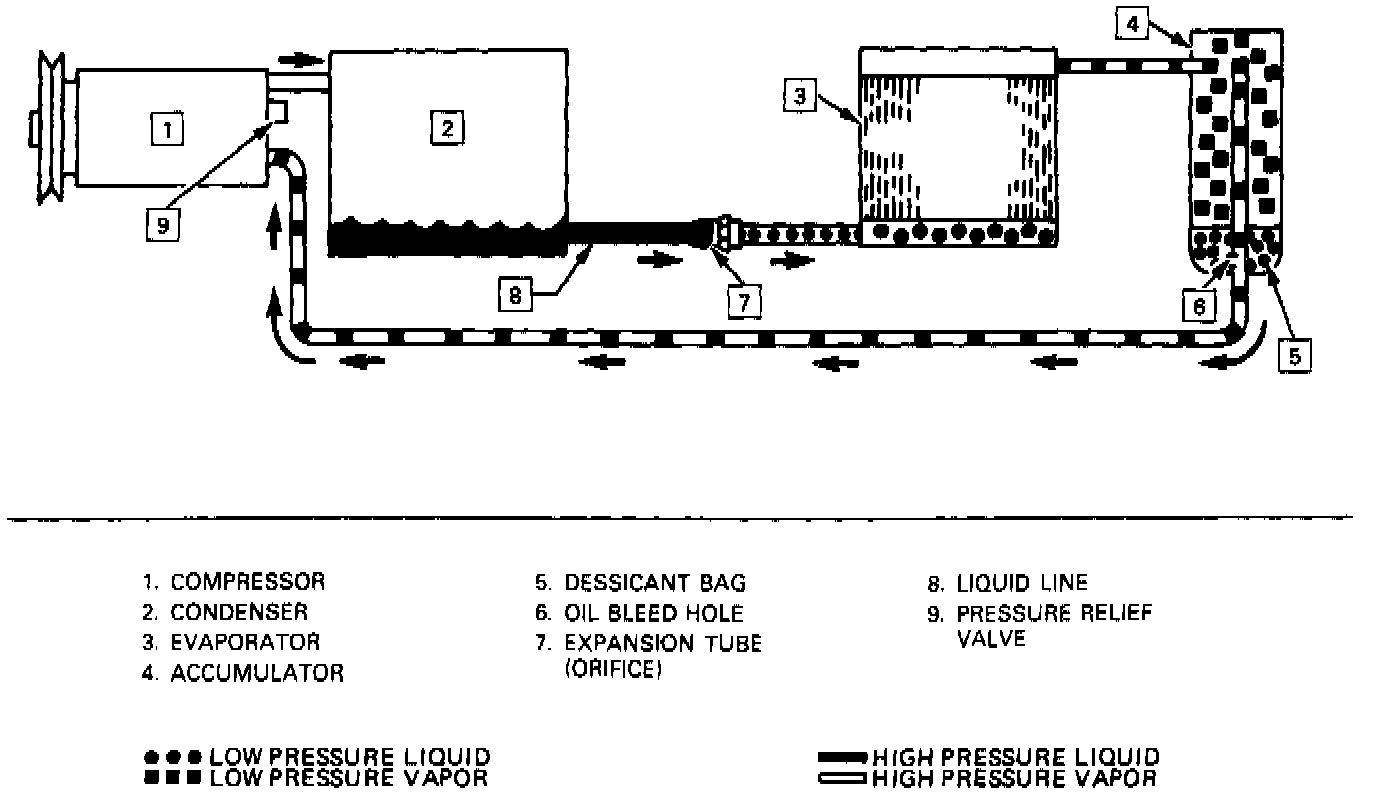
Equalizing Pressure
When the engine is turned "OFF" with the A/C system operating, the refrigerant in the system will flow from the high pressure side of the expansion tube (orifice) to the low pressure side until the pressure is equalized. This may be detected as a faint sound of liquid flowing (hissing) for 30 to 60 seconds and is a normal condition.
A/C Control Assembly:

CONTROLS
Control Assembly
The operation of the A/C system is controlled by the buttons and the lever on the control head. The compressor clutch and blower are connected electrically to the control head by a wiring harness. The blower circuit is open in the off mode and air flow is provided by the four blower speeds available in the remaining modes. Cooled and dehumidified air is available in the max, normal, bi-level, defog and defrost modes.
Modes Of Operation
The temperature lever controls the temperature valve through a potentiometer in the control and electric motor attached to the heater module. The modes of operation are controlled by pushbuttons that send an appropriate electrical signal to the five solenoid valves that control the flow of vacuum on the various vacuum valve positioning actuators. Blower speeds (low, medium 1, medium 2, and high) are controlled in all modes (except off) by two soft-touch pushbuttons on the control head. The blower is turned off in the "OFF" mode of operation. Temperature valve position is independent of mode selection.
AIR DISTRIBUTION SYSTEM
Control of air through the system is regulated by vacuum. At various positions of the buttons and levers on the control assembly, mode valves mix and direct cooled, heated and outside air through the air ducts.
The flow of air from the heater system during the various modes of operations is as follows:
Off - Floor outlet, forced air only.
Max - Instrument panel outlets recirculation air Norm - Instrument panel outlets outside air.
BI/Level - Instrument panel outlets and floor outlets.
Heater - Floor outlets and a small amount from defroster duct.
Defog - Equal amounts floor and defrost.
Defrost - Defroster outlets
The electric engine cooling fan on some cars is not part of the A/C system; however, the fan is operational any time the A/C system control is in max., norm., or hi-level modes. The operation of the cooling fan is controlled by the ECM through the cooling fan relay.
Complete wiring diagrams are found under Diagrams for the appropriate component and diagnosis for the A/C Electrical System is located under Testing and Inspection..