Linear Shift Assembly - Removal - Column Shift
Tilt Steering Column (Part 1 Of 2):
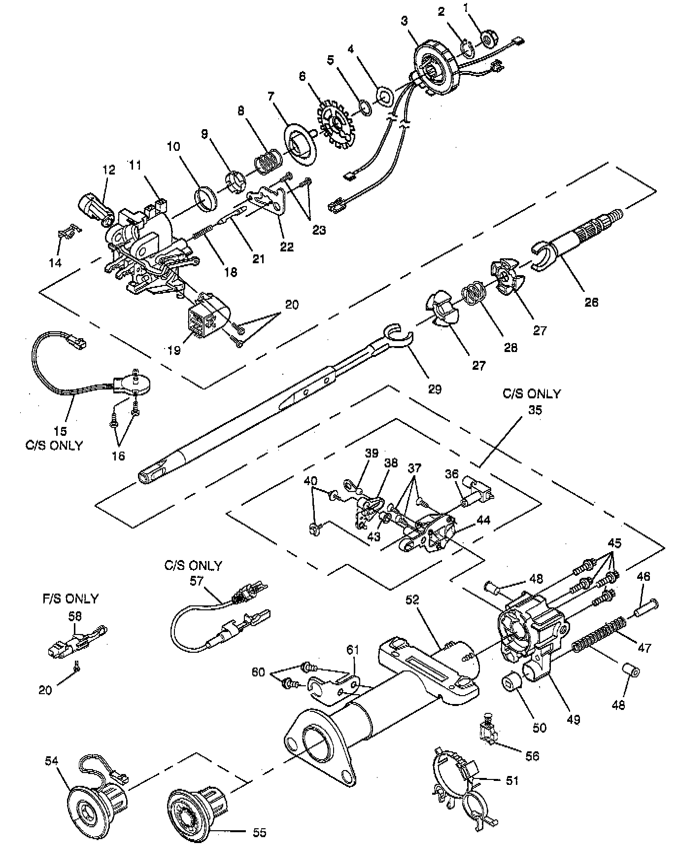
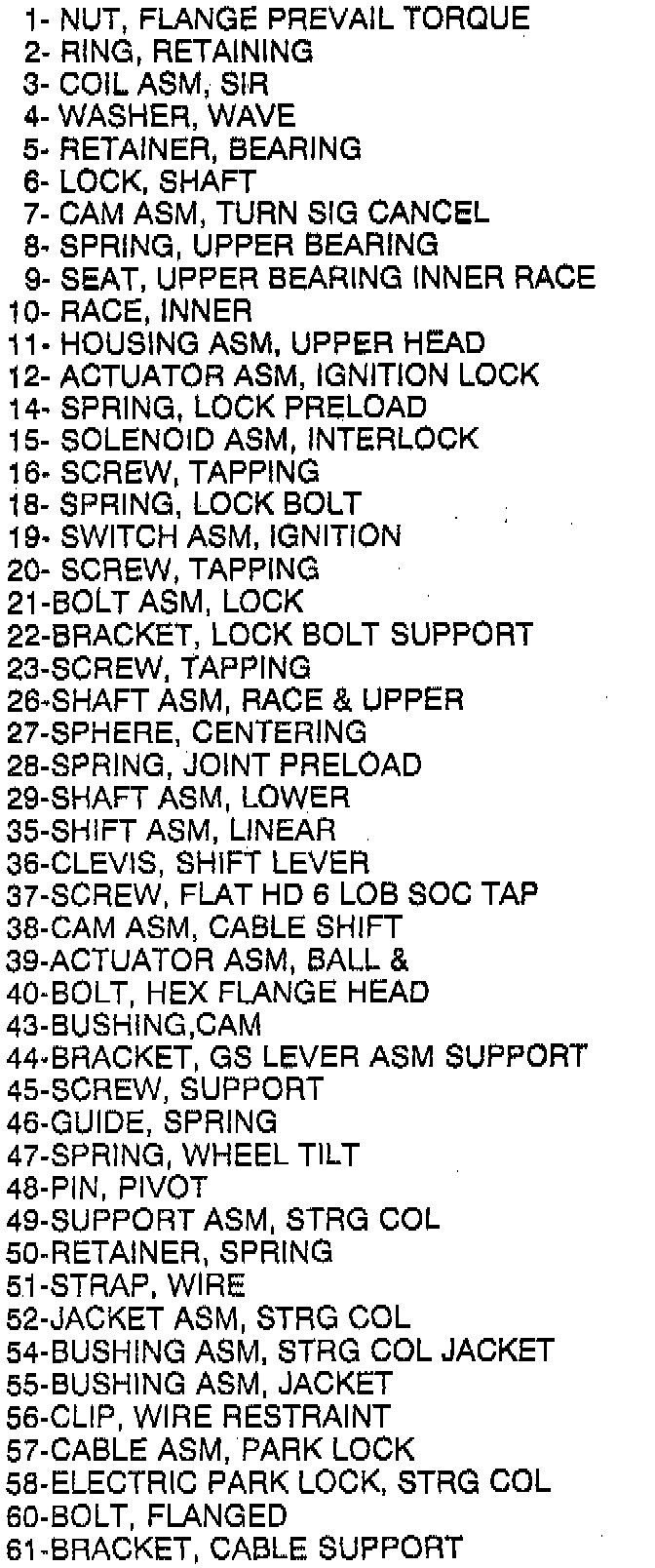
Tilt Steering Column - Legend (Part 2 Of 2):
^ Tools Required:
- J 41352 Modular Column Holding Fixture
- Or Equivalent
NOTICE: Linear shift assembly (35) may be removed as an assembly or certain components may be disassembled as necessary to do repairs. Remove or disassemble only those components necessary to do repairs.
Removing Linear Shift Assembly:

REMOVE OR DISCONNECT
1. Do all steps, refer to LOWER SHROUD, UPPER SHROUD.
2. Transaxle cable from lower shift cable ball stud on cable shift cam assembly (38).
3. Three flat head 6-lobed socket tap screws (37).
^ Shift column to "NEUTRAL" position to gain access to lower socket tap screw (37).
4. Linear shift assembly (35) from column.
INSTALL OR CONNECT
NOTICE: Use the correct fastener in the correct location. Replacement fasteners must be the correct part number for that application. Fasteners requiring replacement or fasteners requiring the use of thread locking compound or sealant are identified in the service procedure. Do not use paints, lubricants, or corrosion inhibitors on fasteners or fastener joint surfaces unless specified. These coatings affect fastener torque and joint clamping force and may damage the fastener. Use the correct tightening sequence and specifications when installing fasteners in order to avoid damage to parts and system.
1. Linear shift assembly (35) to column.
2. Three flat head 6-lobed socket screws (37).
^ Linear shift assembly (35) must be out of "PARK" position to install lower socket screw (37).
^ Tighten screws (37) to 10 Nm (89 lb in).
3. Transaxle cable to lower shift cable ball stud on cable shift cam assembly (38).
Removing Linear Shift Assembly:

^ Adjust park lock cable assembly (57).
A. Route cable from shift assembly to housing assembly, steering column.
B. With key in run position and shift lever in park detent, snap connector body of cable assembly to housing. Make sure locking tab is fully engaged into housing.
C. Push and hold cable sheath at adjuster body toward shifter assembly. Turn key to off-lock position and pull key half way out of lock cylinder, release cable sheath.
D. Allow cable to reach equilibrium, lock cable adjuster.
^ Inspect the park lock cable assembly (57).
A. With lock cylinder in "OFF-LOCK" position, gear shift lever should not be able to shift out of "PARK" position.
B. Insert key and turn to "RUN" position.
C. Shifter in "NEUTRAL" position.
D. With gear shift in "NEUTRAL" position, lock cylinder should not be able to go into "OFF-LOCK" position.
E. Shifter in "PARK" position.
F. Lock cylinder in "OFF-LOCK" position and remove key.
4. Do all steps, refer to LOWER SHROUD UPPER SHROUD.