Sub Section C - Mid Column - Column Shift
Sub-Section C - Mid Column procedure also includes procedures for the following components:- Steering column housing ASM
- Steering wheel lock shoe
- Switch actuator sector
- Switch actuator rack
- Bearing ASM
- Lock bolt
- Steering column housing support assembly
- Steering shaft assembly
- Shift tube assembly
^ Tools Required:
- J 23653-SIR Lock Plate Compressor
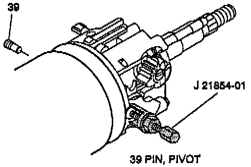
- J 21854-01 Pivot Pin Remover
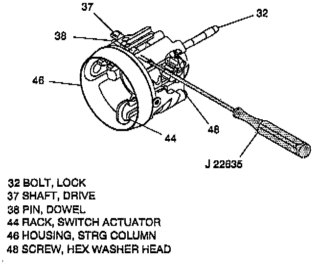
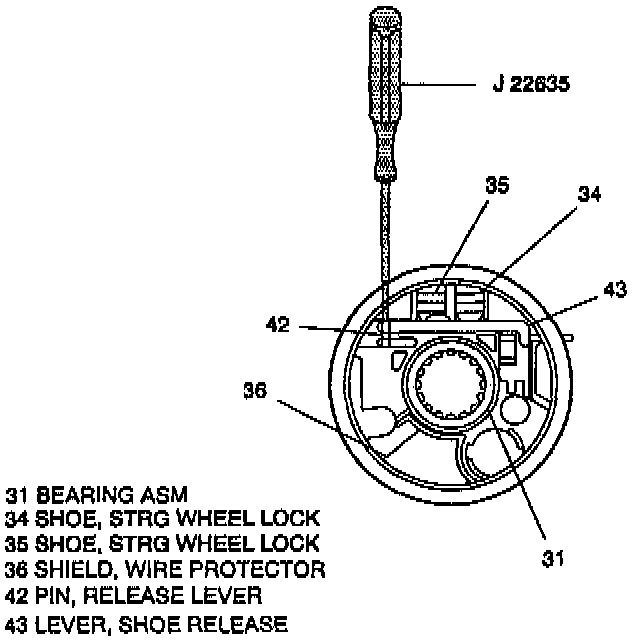
- J 22635 Lock Shoe and Release Lever Pin Remover and Installer
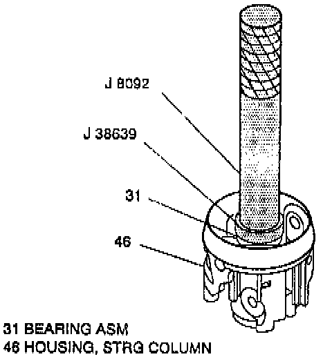
- J 8092 Driver Handle
- J 38639 Steering Column Housing Bearing Installer
- J 23072 Shift Tube Remover
- J 23073-01 Shift Tube Installer
- Or Equivalents
NOTE: Before doing any service procedures, removal of Inflator Module and Steering Wheel is needed. (Refer to service procedures in "Steering Wheel And Column On-Vehicle Service".)
REMOVE OR DISCONNECT


1. Disable the Supplemental Inflatable Restraint (SIR) system; refer to "Disabling the SIR System".
2. Negative (-) battery cable.
3. Steering column from vehicle.
CAUTION: Once steering column is removed from vehicle, the column is extremely susceptible to damage. Dropping steering column assembly on its end could collapse steering shaft or loosen plastic injections which maintain column rigidity. Leaning on steering column assembly could cause jacket to bend or deform. Any of the above damage could impair steering column's collapsible design. If it is necessary to remove steering wheel, use only the specified steering wheel puller. Under no conditions should the end of shaft be hammered on as hammering could loosen plastic injections which maintain steering column rigidity.
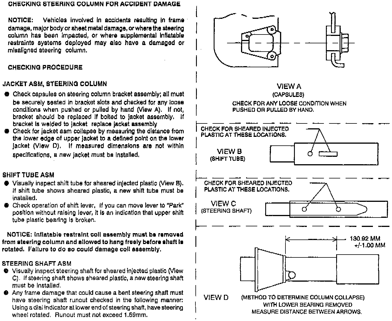
^ Inspect the steering column for accident damage.
4. Do steps 3 through 22 under "REMOVE OR DISCONNECT", refer to Sub Section A.
5. Do steps 2 through 10 under "REMOVE OR DISCONNECT", refer to Sub Section B.
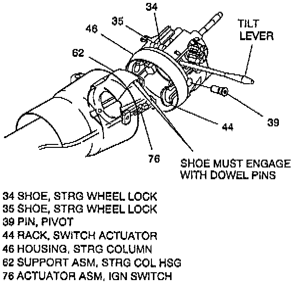
6. Pivot pins (39) using J 21854-01.
^ Reinstall tilt lever. Refer to "Steering Wheel And Column On-Vehicle Service."
7. Steering column housing (46).
^ Pull back on tilt lever and pull steering column housing (46) down and away from column.
NOTE: Remove only those components necessary to do repairs.
DISASSEMBLE STEERING COLUMN HOUSING
^ Disassemble - Steering Column Housing Assembly:
a. Bearing assembly (31).
b. Hexagon washer head screw (48).
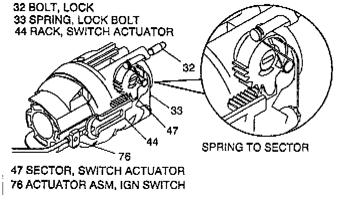
c. Lock bolt spring (33).
d. Lock bolt (32).
e. Switch actuator rack (44) and rack preload spring (45).
f. Drive shaft (37).
g. Switch actuator sector (47).
h. Release lever pin (42) using J 22635.
i. Shoe release lever (43).
j. Release lever spring (41).
k. Dowel pin (38) using J 22635.
l. Steering wheel lock shoes (34) and (35).
m. Shoe springs (40).
ASSEMBLE STEERING COLUMN HOUSING
^ Assemble - Steering Column Housing Assembly:
a. Shoe springs (40).
b. Steering wheel lock shoes (34) and (35).
c. Dowel pin (38) using J 22635.
d. Release lever spring (41).
e. Shoe release lever (43).
f. Release lever pin (42) using J 22635.
g. Switch actuator sector (47).
h. Drive shaft (37).
i. Rack preload spring (45).
j. Switch actuator rack (44) to sector (47).
k. Bearing assembly (31) lubricated with lithium grease to column housing (46) using J 38639 and J 8092.
l. Lock bolt (32).
m. Lock bolt spring (33).
n. Hexagon washer head screw (48).
^ Tighten screw (48) to 4.0 Nm (35 lb in).
8. With a large blade screwdriver carefully pry:
^ Actuator end fitting from stud on shift lever.
^ Adjuster block from mounting stud on lower support bracket (94).
9. Axial Positive assurance connector (93) from (BTSI) actuator (96).
^ Wire connection from (13TSI) actuator (96).
^ Adjustment retaining clip (97).
10. Bearing & seal retainer (83).
^ Retainer washer assembly (84) from retainer (83).
11. Lower spring retainer (92).
^ Dispose of retainer (92).
12. Lower bearing spring (91).
13. Lower bearing seat (90).
14. Hex flanged head bolts (95).
15. Steering column lower support (94) & screws (88).
16. Adapter & bearing assembly (87).
17. Steering shaft assembly (55).
^ Inspect the steering shaft assembly (55) for accident damage.
NOTE:
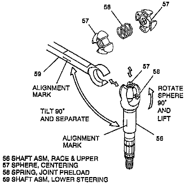
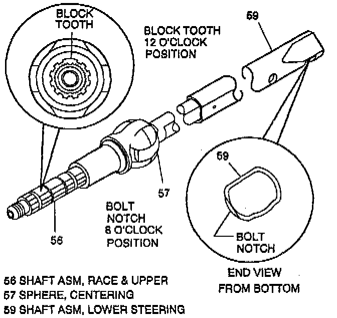
^ Mark race & upper shaft assembly (56) and lower steering shaft assembly (59) to ensure proper assembly. Failure to assemble properly will cause steering wheel to be turned 180°.
^ Remove only those components necessary to do repairs.
DISASSEMBLE STEERING SHAFT ASSEMBLY
^ Disassemble - Steering Shaft Assembly:
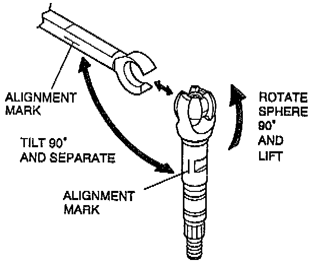
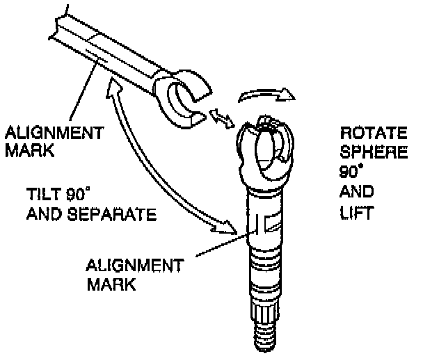
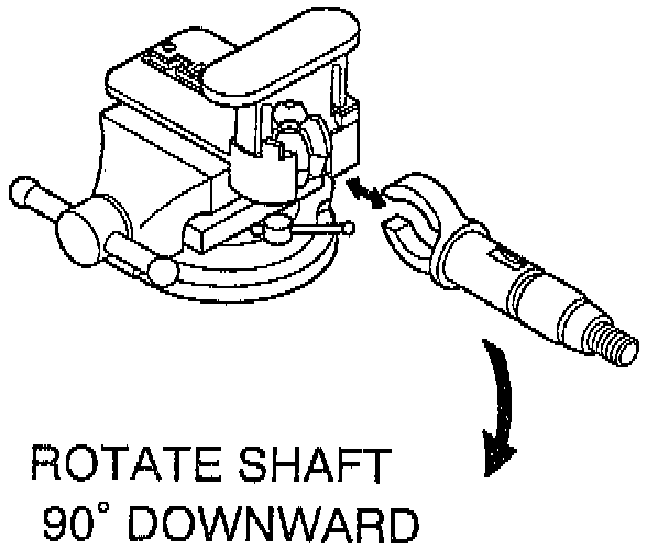
a. Race & upper shaft assembly (56), from lower steering shaft assembly (59).
^ Tilt 90° to each other and disengage.
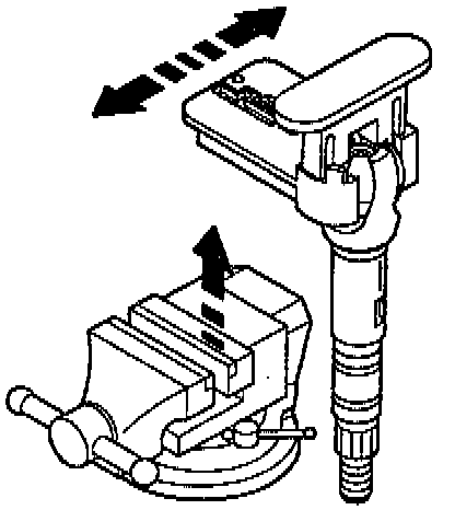
b. Centering sphere (57) from upper shaft assembly (56).
^ Rotate sphere 90° and slip out.
c. Joint preload spring (58) from centering sphere (57).
1. Disassemble the lower steering shaft assembly from the upper shaft assembly.
NOTE: Mark upper shaft assembly and lower steering shaft assembly to ensure proper assembly. Failure to assemble properly will cause steering wheel to be turned 180°.
2. Tilt the lower steering shaft assembly 90° to and upper shaft assembly and disengage.
3. If necessary, remove and discard the old centering sphere and spring.
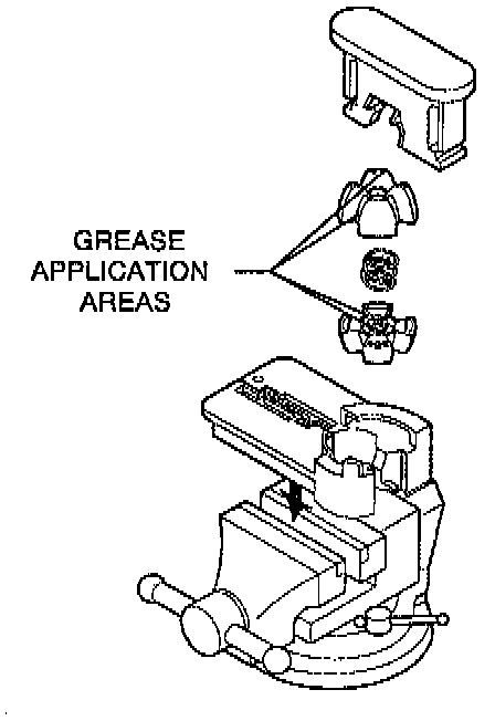
4. Grease the sphere with lithium grease. Grease the lower half of the sphere in the upper shaft assembly engagement areas. Grease the upper half of the sphere in the shaft engagement areas opposite to the greased areas of the lower half of the sphere.
5. Place the base of the tool in a vise. Then place (in order shown) the bottom half of the new centering sphere, the new spring, the top half of the new centering sphere, and the driver in the Centering Sphere Installer tool #J41688.
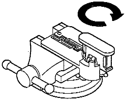
6. Compress the spring and rotate the driver 90° in the clockwise direction.
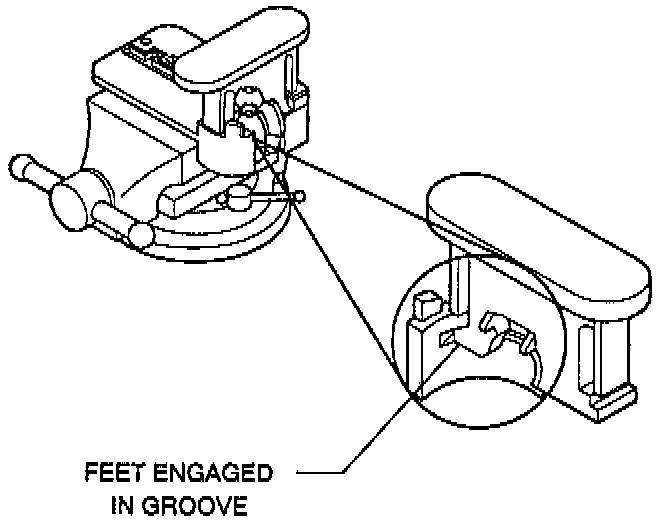
^ Make sure that the feet of the driver slide into grooves in the base. Rotate driver until arms lock in place.
7. Once sphere is locked in place, attach the upper shaft assembly.
^ After the upper shaft assembly is firmly attached to the centering sphere, rotate the shaft 90° downward locking the centering sphere in place.
8. Remove the centering sphere installer and the upper shaft assembly from the vise. Disassemble the tool by separating the base. After the tool is dissembled, the shaft with the attached sphere can be removed.
9. Apply lithium grease to the exposed shaft engagement area and then install the lower shaft assembly.
ASSEMBLE STEERING SHAFT ASSEMBLY
^ Assemble the Steering Shaft Assembly:
a. Joint preload spring (58) to two centering sphere (57).
b. Centering sphere (57).
^ Lubricate with lithium grease, slip into upper shaft assembly (56), and rotate sphere 90°.
c. Upper shaft assembly (56) to lower steering shaft assembly (59).
^ Line up marks and tilt assemblies 90° to each other.
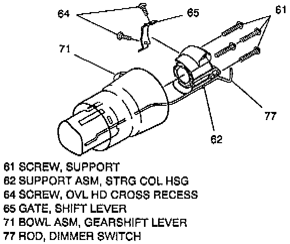
18. Support screws (61).
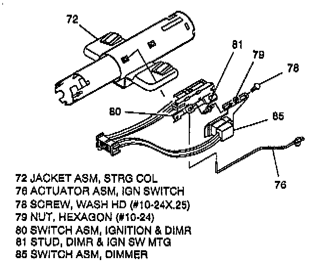
19. Steering column housing support assembly (62) with dimmer switch rod (77) from steering column jacket assembly (72).
^ Rod (77) from support (63).
20. Oval head cross recess screws (64) and shift lever gate (65) from support (63).
21. Hexagon nut (79) and washer head screw (78).
22. Dimmer switch assembly (85).
23. Mounting stud (81).
24. Ignition & dimmer switch assembly (80) with ignition switch actuator assembly (76).
^ Switch actuator assembly (76) from switch assembly (80).
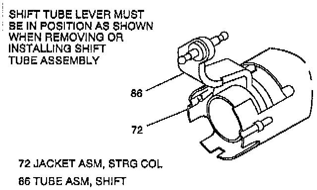
CAUTION: Shift tube lever must be in position to clear jacket assembly (72) when removing shift tube (86). Forcing lever against jacket may cause damage to jacket assembly (72).
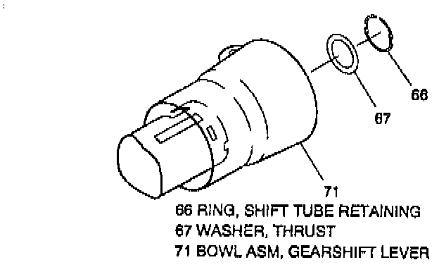
25. Shift tube retaining ring (66).
26. Thrust washer (67).
27. Shift tube assembly (86) using J 23072.
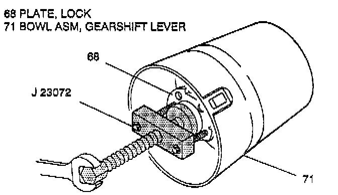
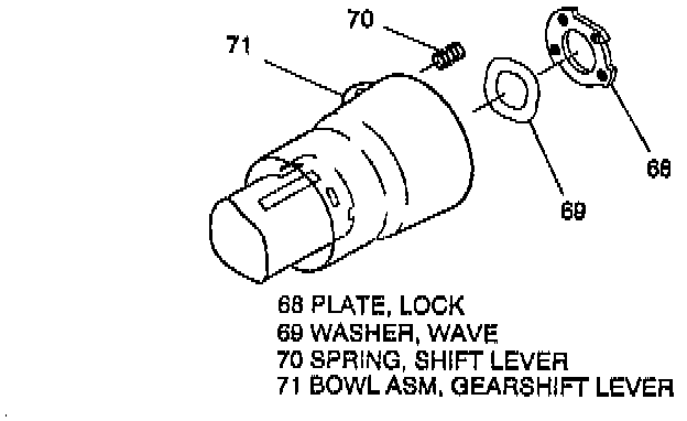
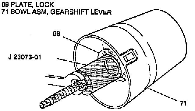
28. Lock plate (68).
29. Wave washer (69).
30. Gearshift lever bowl (71).
31. Shift lever spring (70) from bowl (71).
INSTALL OR CONNECT
CAUTION: Always use the correct fastener in the correct location. When you replace a fastener, use ONLY the exact part number for that application. The Manufacturer will call out those fasteners that require a replacement after removal. The Manufacturer will also call out the fasteners that require thread lockers or thread sealant. UNLESS OTHERWISE SPECIFIED, do not use supplemental coatings (paints, greases, or other corrosion inhibitors) on threaded fasteners or fastener joint interfaces. Generally, such coatings adversely affect the fastener torque and the joint clamping force, and may damage the fastener. When you install fasteners, use the correct tightening sequence and specifications. Following these instructions can help you avoid damage to parts and systems.
CAUTION: Ensure all fasteners are securely seated before applying needed torque. Failure to do so may result in component damage or malfunctioning of steering column.
1. Spring (70) to bowl (71).
2. Bowl (71) to jacket (72).
3. Wave washer (69).
^ Lubricate with lithium grease.
4. Lock plate (68).
CAUTION: Shift tube lever must be in position to clear jacket assembly (72) when installing shift tube (86). Forcing lever against jacket may cause damage to jacket assembly (79).
5. Shift tube (86) using J 23073-01.
6. Thrust washer (67).
7. Retaining ring (66).
8. Gate (65) and screws (64) to support (63).
^ Tighten screws (64) to 3.7 Nm (33 lb in).
9. Dimmer switch rod (77) to column housing support assembly (62).
10. Support assembly (62) and support screws (61).
^ Tighten screws (61) to 10.0 Nm (88 lb in).
11. Steering shaft assembly (55) to jacket assembly(72).
^ Lubricate with lithium grease.
12. Ignition switch actuator assembly (76).
13. Tilt lever. Refer to "Steering Wheel And Column On-Vehicle Service."
14. Column housing (30) to column.
a. Position column housing (30) and align switch actuator rack (44) with pin on end of ignition switch actuator assembly (76).
b. Pull back on tilt lever, pushing column housing (30) onto column housing support assembly (62).
c. Release tilt lever to lock shoes (34) and (35) onto dowel pins.
d. Remove tilt lever. Refer to "Steering Wheel And Column On-Vehicle Service."
15. Pivot pins (39).
^ Lubricate with lithium grease.
^ Press pin until firmly seated, two places.
16. Adapter & bearing assembly (87).
^ Lubricate inner surface with lithium grease.
17. Hexagon washer head tapping screws (88).
^ Tighten screws (88) to 3.4 Nm (30 lb in).
18. Steering col lower support (94) with hex head bolts (95).
^ Tighten screws (95) to 10.5 Nm (93 lb in).
19. Lower bearing seat (90).
20. Lower bearing spring (91).
21. New lower spring retainer (92).
^ Press retainer (92) onto shaft (55) to compress spring (91).
^ Measure the distance from face of adapter & bearing assembly (87) to lower spring retainer (92).
^ Spring height must equal 25.4mm (1.0 inch).
22. Bearing & seal retainer (83).
23. Retainer washer assembly (84) to retainer (83).
24. Actuator assembly (76) to housing support assembly (62).
25. Do steps 1 through 12 under "INSTALL OR CONNECT", refer to Sub Section B.
26. Do steps 1 through 21 under "INSTALL OR CONNECT", refer to Sub Section A.
27. Lock cylinder (20) to "OFF-LOCK" position.
CAUTION: Install ignition switch (80) to jacket (72) with switch in "OFF-LOCK" position. New ignition switch will be pinned in "OFF-LOCK" position. Remove plastic pin after switch is assembled to column. Failure to do so may cause switch damage.
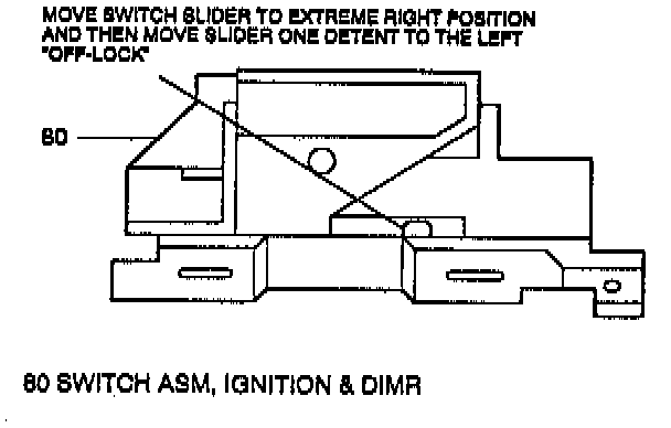
^ Adjust the ignition switch assembly (80).
a. Move switch slider to extreme right position.
b. Move switch slider one detent to left "OFFLOCK" position.
c. Install 3/32 inch drill bit in hole on switch to limit travel.
28. Ignition switch assembly (80) and mounting stud (81).
^ Tighten stud (81) to 4.0 Nm (35 lb in).
29. Remove drill bit from ignition switch (85).
30. Dimmer switch assembly (85).
^ Ground wire with ring terminal from turn signal switch wire harness to stud (81).
31. Washer head screw (78) and hexagon nut (79).
^ Tighten finger tight.
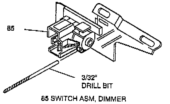
^ Adjust the dimmer switch (85).
a. Place a 3/32-inch drill bit in hole on switch to limit travel.
b. Position switch on column and push against dimmer switch rod to remove all lash.
c. Remove drill bit.
^ Tighten screw (78) and nut (79) to 4.0 Nm (35 lb in).
32. Do all steps under "INSTALL OR CONNECT", refer to Sub Section D, Electrical (BTSI) Actuator.