Hydraulic System: Service and Repair
- Tools Required- J 29532 Diaphragm Type Brake Bleeder
- J 35589 Brake Bleeder Adapter
CAUTION: Use only SUPREME 11 or equivalent DOT 3 brake fluid from a clean, sealed container. Do not use fluid from an open container that may be contaminated with water. Improper or contaminated fluid will result in damage to components or loss of braking, with possible personal injury.
NOTICE:
- Pressure bleeding equipment must be of the diaphragm type. It must have a rubber diaphragm between the air supply and the brake fluid to prevent air, moisture, and other contaminants from entering the hydraulic system.
- Avoid spilling brake fluid on any of the vehicle's painted surfaces, wiring, cables, or electric connectors. Brake fluid will damage the paint and the electrical connections. If any fluid is spilled on the vehicle, flush the area to lessen the damage.
IMPORTANT:
- The presence of dark brake fluid is NOT an indication of brake fluid contamination. The presence of dark brake fluid is caused by normal brake system rubber component wear. One of the most common indications of brake fluid contamination is brake system rubber component swelling and/or deterioration.
- Flush the hydraulic brake system if there is any doubt about the condition of the fluid in the system or if the brake fluid has been contaminated (mixed with anything other than the recommended brake fluid).
- Ensure that the master cylinder brake fluid level does not drop to the bottom of the master cylinder reservoir. You will be instructed to Inspect and fill the master cylinder reservoir at times during this procedure. However, the actual frequency of master cylinder reservoir filling REQUIRED will depend on the amount of fluid that is released. If the brake fluid level drops to the bottom of the master cylinder reservoir, start the bleed procedure again at Step 1.
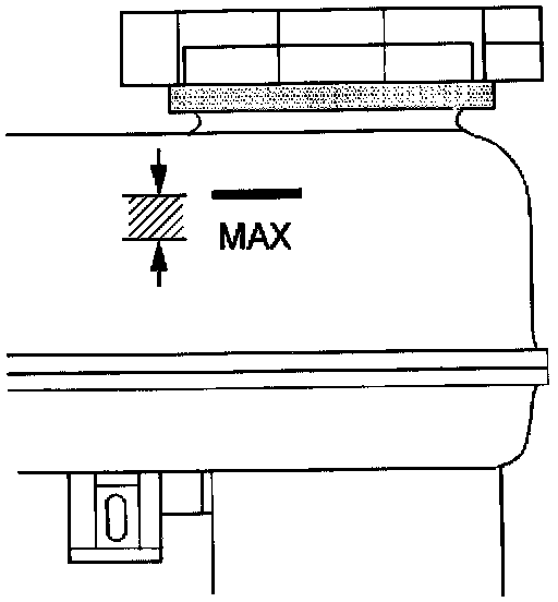
1. Inspect and fill the master cylinder reservoir to the proper level as necessary. Refer to "Master Cylinder Reservoir Filling" in Master Cylinder, Brakes..
2. Assemble the following components to the J 35589
2.1. 1/4 inch to 1/8 inch adapter
2.2. Assemble the 1/8 Inch 90 Degree Pipe Fitting Elbow to the
2.3. 1/8 inch quick connect fitting
3. Install the J 35589 to the master cylinder reservoir.
4. Connect the J29532to the J35589.
5. Adjust the J29532 to 35-70 kPa (5-10 psi).
6. Wait approximately 30 seconds, then inspect the entire hydraulic brake system in order to ensure that there are no existing brake fluid leaks. Repair any brake fluid leaks.
7. Adjust the J 29532 to 205-240 kPa (30-35 psi).
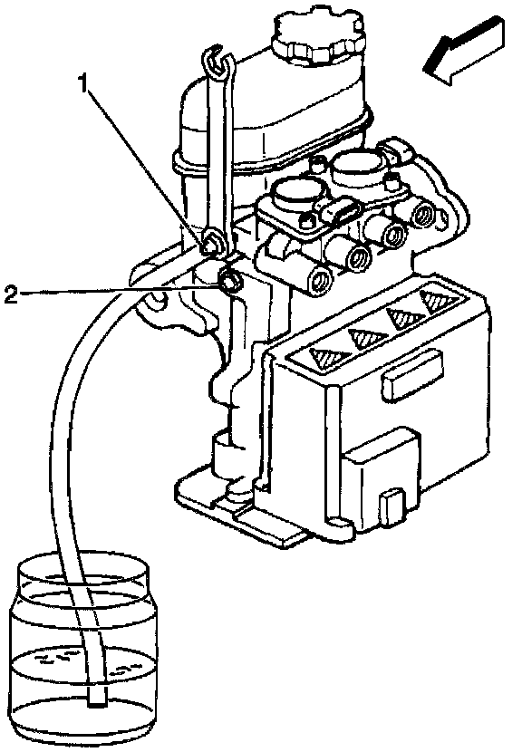
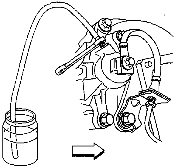
8. Install a clear plastic bleeder hose to the ABS modulator REAR bleeder valve (1).
9. Submerge the opposite end of the clear plastic bleeder hose in a clean container partially filled with clean brake fluid.
10. Slowly open the ABS modulator bleeder valve in order to allow the brake fluid to flow.
11. Close the ABS modulator bleeder valve when either of the following is observed:
- Clean brake fluid is noticed
- 118 ml (4 oz) of brake fluid is released
12. Remove the clear plastic bleeder hose from the ABS modulator bleeder valve.
- Tighten the previously bled ABS modulator bleeder valve to 9 Nm (80 inch lbs.).
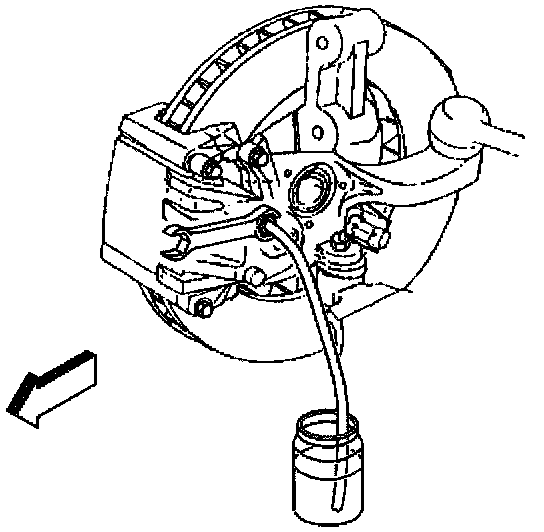
13. Install the clear plastic bleeder hose to the ABS modulator FRONT bleeder valve (2).
14. Repeat Steps 9 through 11.
15. Raise and suitably support the vehicle.
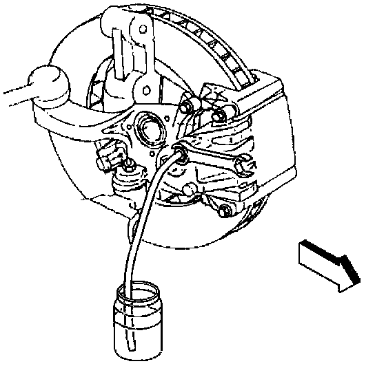
16. Install the clear plastic bleeder hose to the RIGHT REAR bleeder valve.
17. Submerge the opposite end of the clear plastic bleeder hose in a clean container partially filled with clean brake fluid.
18. Slowly open the wheel cylinder bleeder valve in order to allow the brake fluid to flow.
19. Close the bleeder valve when either of the following is observed:
- Clean brake fluid is noticed
- 235 ml (8 oz) of brake fluid is released
20. Remove the clear plastic bleeder hose from the bleeder valve.
- Tighten the wheel cylinder bleeder valve to 11 Nm (97 inch lbs.).
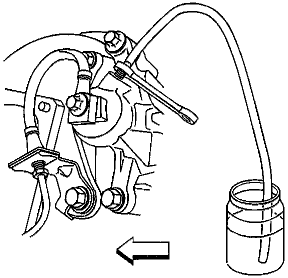
21. Install the clear plastic bleeder hose to the LEFT FRONT brake caliper bleeder valve.
22. Submerge the opposite end of the clear plastic bleeder hose in a clean container partially filled with clean brake fluid.
23. Slowly open the brake caliper bleeder valve in order to allow the brake fluid to flow.
24. Close the brake caliper bleeder valve when either of the following is observed:
- Clean brake fluid is noticed
- 235 ml (8 oz) of brake fluid is released
25. Remove the clear plastic bleeder hose from the brake caliper bleeder valve.
- Tighten the brake caliper bleeder valve to 13Nm (115 in. lbs.).
26. Install the clear plastic bleeder hose to the LEFT REAR bleeder valve.
27. Submerge the opposite end of the clear plastic bleeder hose in a clean container partially filled with clean brake fluid.
28. Slowly open the wheel cylinder bleeder valve in order to allow the brake fluid to flow.
29. Close the bleeder valve when either of the following is observed:
- Clean brake fluid is noticed
- 235 ml (8 oz) of brake fluid is released
30. Remove the clear plastic bleeder hose from the bleeder valve.
- Tighten the wheel cylinder bleeder valve to 11 Nm (97 inch lbs.).
31. Install the clear plastic bleeder hose to the RIGHT FRONT brake caliper bleeder valve.
32. Submerge the opposite end of the clear plastic bleeder hose in a clean container partially filled with clean brake fluid.
33. Slowly open the brake caliper bleeder valve in order to allow the brake fluid to flow.
34. Close the brake caliper bleeder valve when either of the following is observed:
- Clean brake fluid is noticed
- 235 ml (8 oz) of brake fluid is released
35. Remove the clear plastic bleeder hose from the brake caliper bleeder valve.
- Tighten the brake caliper bleeder valve to 13 Nm (115 inch lbs.).
36. Lower the vehicle.
37. Remove the J 35589 from the master cylinder reservoir.
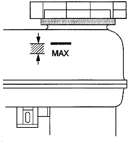
38. Inspect and fill the master cylinder reservoir to the proper level as necessary. Refer to "Master Cylinder Reservoir Filling" in Master Cylinder, Brakes.
39. Install the master cylinder reservoir cap.
IMPORTANT: After performing the initial hydraulic brake system flushing procedure, replace all of the rubber components which have come in contact with contaminated brake fluid.
40. Perform the following steps:
40.1. Replace the brake hoses. Refer to Brake Hose Replacement - Front or Brake Hose Replacement- Rear.
40.2. Replace or overhaul the master cylinder. Refer to Brake Modulator/Master Cylinder Assembly Replacement or Master Cylinder Overhaul.
40.3. Replace or overhaul the brake calipers. Refer to the following:
^ Brake Caliper Replacement - Front.
^ Brake Caliper Replacement - Rear.
^ Brake Caliper Overhaul - Front.
^ Brake Caliper Overhaul - Rear.
40.4. Replace the antilock brake system modulator. Refer to Brake Modulator/Master Cylinder Assembly Replacement.
40.5. Flush the hydraulic brake system once again, then bleed the hydraulic brake system. Refer to "Hydraulic Brake System Bleeding" in Brake Bleeding.