Connectors, Handling and Checking
Connectors, Handling And Checking
Handling
1. When detaching connectors with locks, it is essential that the lock is released before the connector is detached. Ensure the connector locks properly when connecting.
Example of some different connector types used in the car:
1. A. Pull out the slide to unlock the connector.
After attaching the connector lock it by pressing in the slide.
NOTE: Using a small screwdriver will help to unlock the connector.

1. B. Press in the lock tab to unlock the connector.
Make sure the connector is locked properly when connecting.

1. C. Pull out the slide to unlock the connector.
After attaching the connector lock it by pressing in the slide.

1. D. Press in the brace catch and push forward the brace.
Push back the brace to lock the connector after connecting.
NOTE: Make sure the brace is locked in the right position to ensure good contact between connectors.

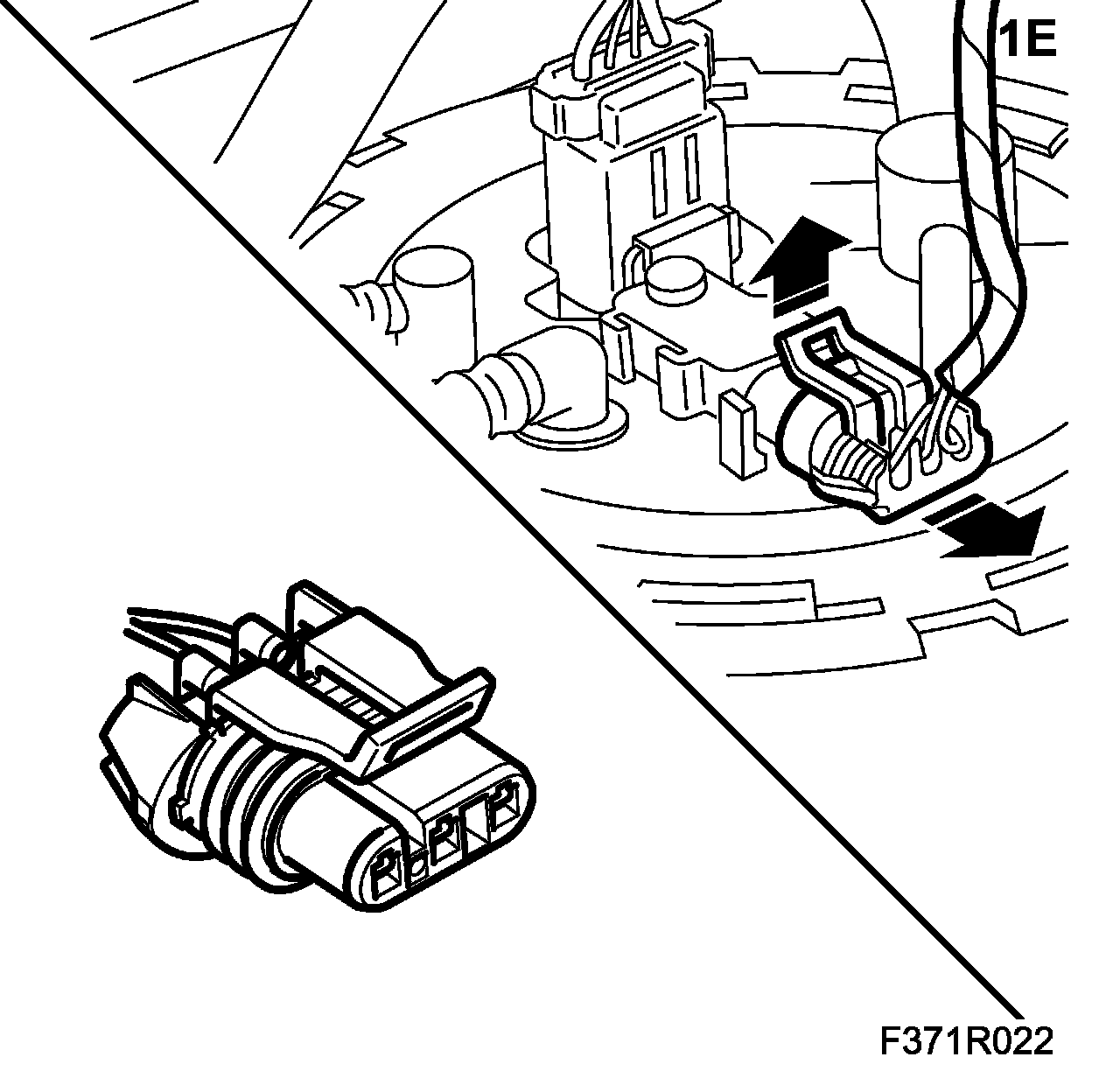
1. E. Lift up the lock tab to unlock the connector.
Make sure the connector is locked properly when connecting.
1. F. Press in the connector lock tab to release the brace. Release the connector slide while pushing the brace forward.
NOTE: The connector may be damaged if too much force is used to push forward the brace without first releasing the slide.
Push back the brace to lock the connector after connecting.

2. Ground yourself by touching the car body/engine before removing or fitting any of the connectors on the car's control modules.
3. Never pull the wiring harness when removing a connector.

4. Never touch the pins on the control module with your hands or clothes.
IMPORTANT:
- Incorrect handing or the use of the wrong tool can damage the sleeves in the connector.
- Use a test cable (part no. 86 12 731) of the correct size to avoid damaging the sleeves in the connector.
5. When testing only probe tips intended for the purpose are to be used to avoid damaging the contacts. Use a test cable (part no. 86 12 731) of the right size.

6. Connectors may only be repaired when using specified special tools and spare parts.
7. The following connectors must not be repaired:
- Screened wires/coaxial cables (e.g. ESP sensor cable)
- Airbag system and pyrotechnical seat-belt tensioner system
- High tension cable (e.g. ignition system, xenon lamp).
Checking
1. Check for any contact problems in connections.
2. Check contacts, connectors and crimp connections with respect to oxidation, loose pins and pin clamping force.
IMPORTANT:
- Incorrect handing or the use of the wrong tool can damage the sleeves in the connector.
- Use a test cable (part no. 86 12 731) of the correct size to avoid damaging the sleeves in the connector.
3. To check the connector clamping force, use a test cable with the right pin size (from kit 86 12 731).
NOTE: Using a test cable that is too big will damage connector sleeves.
- Insert the test cable pin into the connector pin to feel the clamping force of the pins in question. Poor clamping force of the connector pins can cause bad contact.

- Also check that the engagement height of the pin is the same as the other pins in the connector. An engagement height that is too low could be an indication of a loose pin in the connector, which could cause bad contact.

4. Check wires and connections for open circuits.
5. Check wiring harness, connectors and ground connections.