Engine Assembly, Removal
ENGINE ASSEMBLYCOMPONENTS:

COMPONENTS:

COMPONENTS:

COMPONENTS:

COMPONENTS:

COMPONENTS:


COMPONENTS:

REMOVAL
1. DISCHARGE FUEL SYSTEM PRESSURE
2. DISCONNECT CABLE FROM NEGATIVE BATTERY TERMINAL
CAUTION: Wait at least 90 seconds after disconnecting the cable from the negative (-) battery terminal to prevent airbag and seat belt pretensioner activation.
3. REMOVE ENGINE UNDER COVER RH
4. REMOVE ENGINE UNDER COVER LH
5. DRAIN ENGINE COOLANT
6. REMOVE FRONT WHEEL

7. REMOVE NO. 2 CYLINDER HEAD COVER
a) Remove the 4 nuts and No. 2 cylinder head cover.
8. REMOVE BATTERY
9. REMOVE AIR CLEANER
10. DISCONNECT FUEL TUBE
11. DISCONNECT ACCELERATOR CONTROL CABLE
12. REMOVE RADIATOR
13. DISCONNECT TRANSMISSION CONTROL CABLE (for Manual Transaxle)
14. DISCONNECT TRANSMISSION CONTROL CABLE (for Automatic Transaxle)
15. DISCONNECT CLUTCH RELEASE CYLINDER (for Manual Transaxle)
16. DISCONNECT UNION TO CHECK VALVE HOSE
a) Disconnect the union to check valve hose for the brake booster.

17. DISCONNECT HEATER WATER INLET HOSE
a) Disconnect the heater water inlet hose from the air conditioner tube.

18. DISCONNECT HEATER WATER OUTLET HOSE
a) Disconnect the heater water outlet hose from the air conditioner tube.
19. DISCONNECT ENGINE WIRE
a) Remove the glove compartment door.
b) Disconnect the engine wire harness from the ECM and junction block.
c) Pull out the engine wire.
d) Disconnect the engine wire from the engine room junction block.
e) Remove the body ground.
20. REMOVE GENERATOR V BELT
21. REMOVE COOLER COMPRESSOR
22. REMOVE FLOOR PANEL BRACE FRONT
23. REMOVE EXHAUST PIPE FRONT
24. DISCONNECT STEERING INTERMEDIATE SHAFT

25. REMOVE FRONT AXLE HUB LH NUT
a) Remove the clip and nut.
b) Using SST and a hammer, unstake the lock nut.
SST 09930-00010
NOTICE:
^ When removing the nut, unstake the lock nut completely.
^ Do not damage the threads of the drive shaft.
^ Do not use SST with the tip sharpened.
^ Set SST to the groove with the flat face facing upward.
c) Using a 30 mm socket wrench, remove the lock nut.
HINT: Perform the same procedure as above on the opposite side.

26. DISCONNECT SPEED SENSOR FRONT LH (w/ABS)
a) Remove the bolt and disconnect the speed sensor from the steering knuckle.
HINT: Perform the same procedure as above on the opposite side.

27. DISCONNECT TIE ROD END LH
a) Using SST, disconnect the tie rod end from the steering knuckle.
SST 09628-62011
NOTICE: Do not damage the dust cover of the ball joint.
HINT: Perform the same procedure as above on the opposite side.

28. DISCONNECT FRONT SUSPENSION ARM LOWER LH
a) Using SST, disconnect the front suspension arm lower from the steering knuckle.
SST 09628-00011
HINT: Perform the same procedure as above on the opposite side.

29. DISCONNECT FRONT DRIVE SHAFT LH
a) Using a plastic-faced hammer, detach the drive shaft from the axle hub by tapping the drive shaft.
HINT: Perform the same procedure as above on the opposite side.

30. REMOVE ENGINE AND TRANSAXLE ASSEMBLY
a) Set the engine lifter.
b) Remove the bolt which is used to fix the liquid tube to the engine mounting insulator RH.
c) Remove the 5 bolts, nut and engine mounting insulator RH.

d) Remove the 2 bolts and detach the engine mounting bracket from the engine mounting insulator LH.

e) Remove the engine together with the transaxle.
1) Remove the 8 bolts shown in the illustration.
2) Carefully remove the engine assembly from the vehicle.

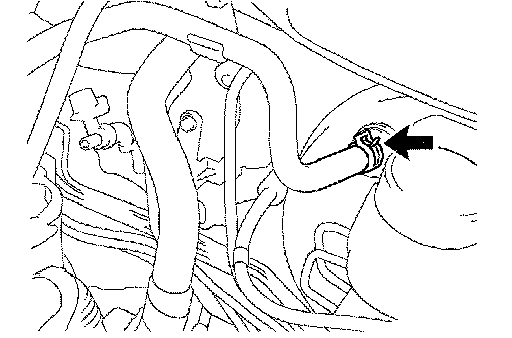
f) Install the 2 engine hangers as shown in the illustration.
Part No.
Part No.:
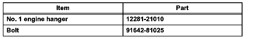
Torque: 40 Nm (408 kgf-cm, 30 ft. lbs.)
g) Attach the engine sling device and hang the engine with the chain block.
31. REMOVE VANE PUMP V BELT
32. REMOVE VANE PUMP
a) Disconnect the power steering oil pressure sensor harness.
b) Remove the 2 bolts and vane pump assembly.

33. REMOVE FRONT SUSPENSION CROSSMEMBER
a) Remove the through bolt.
b) Separate the engine and the transaxle assembly from the suspension crossmember.
34. REMOVE STARTER
35. REMOVE GENERATOR
36. REMOVE MANUAL TRANSAXLE (for Manual Transaxle)
37. REMOVE AUTOMATIC TRANSAXLE (for Automatic Transaxle)
38. REMOVE CLUTCH COVER (for Manual Transaxle)
39. REMOVE CLUTCH DISC (for Manual Transaxle)

40. REMOVE FLYWHEEL (for Manual Transaxle)
a) Hold the crankshaft pulley with SST, and then remove the 6 bolts and flywheel.
SST 09213-58012 (91111-50845), 09330-00021

41. REMOVE DRIVE PLATE (for Automatic Transaxle)
a) Hold the crankshaft pulley with SST, and then remove the 6 bolts and drive plate.
SST 09213-58012 (91111-50845), 09330-00021
42. REMOVE VENTILATION HOSE
43. REMOVE NO. 2 VENTILATION HOSE

44. REMOVE INTAKE MANIFOLD
a) Using several steps, remove the 3 bolts and 2 nuts in the sequence shown in the illustration. Then remove the intake manifold.
b) Remove the gasket from the intake manifold.

45. REMOVE BOOSTER VACUUM TUBE
a) Remove the 2 bolts and booster vacuum tube.

46. REMOVE MANIFOLD SUPPORT BRACKET
a) Remove the 3 bolts and manifold support bracket.
47. REMOVE NO. 1 EXHAUST MANIFOLD HEAT INSULATOR
a) Remove the 4 bolts and exhaust manifold heat insulator.

48. REMOVE EXHAUST MANIFOLD
a) Remove the 3 bolts, 2 nuts and exhaust manifold.

49. REMOVE IGNITION COIL
a) Remove the 4 bolts and pull out the 4 ignition coils.
50. REMOVE NO. 1 WATER BY-PASS PIPE
a) Remove the 2 nuts and 2 bolts, and then remove the water by-pass pipe.

51. REMOVE ENGINE COOLANT TEMPERATURE SENSOR
a) Using SST, remove the sensor.
SST 09817-33190
52. REMOVE KNOCK SENSOR
a) Remove the bolt and sensor.
53. REMOVE ENGINE OIL PRESSURE SWITCH
a) Using SST, remove the switch.
SST 09268-46021
INSPECTION

1. INSPECT INTAKE MANIFOLD
a) Using a precision straightedge and feeler gauge, measure the surface contacting the cylinder head for warpage.
Maximum warpage: 0.10 mm (0.004 inch)
If the warpage is greater than the maximum, replace the manifold.

2. INSPECT EXHAUST MANIFOLD
a) Using a precision straightedge and feeler gauge, measure the surface contacting the cylinder head for warpage.
Maximum warpage: 0.70 mm (0.028 inch)
If the warpage is greater than the maximum, replace the manifold.