Heater Control Switch Circuit
AIR CONDITIONING: AIR CONDITIONING SYSTEM: Heater Control Switch Circuit
Heater Control Switch Circuit
DESCRIPTION
The No. 3 heater control is powered through the HTR-IG fuse. The No. 3 heater control transmits operational signals of each switch to the A/C amplifier.
WIRING DIAGRAM

INSPECTION PROCEDURE
PROCEDURE
1. INSPECT FUSE (HTR-IG)
(a) Remove the HTR-IG fuse from the main body ECU.
(b) Measure the resistance according to the value(s) in the table below.
Standard resistance:

NG -- REPLACE FUSE
OK -- Continue to next step.
2. INSPECT NO. 3 HEATER CONTROL

(a) Measure the resistance.
(1) Remove the No. 3 heater control.
(2) Measure the resistance according to the value(s) in the table below.
Standard resistance:

(b) Check that the indicator light comes on.
(1) Connect the positive (+) lead from the battery to terminal 3 and negative (-) to terminal 4, and check that the indicator light comes on.
OK:
The indicator light comes on.
(c) Reinstall the No. 3 heater control.
NG -- REPLACE NO. 3 HEATER CONTROL
OK -- Continue to next step.
3. CHECK HARNESS AND CONNECTOR (NO. 3 HEATER CONTROL - BATTERY)
(a) Disconnect the C20 No. 3 heater control connector.
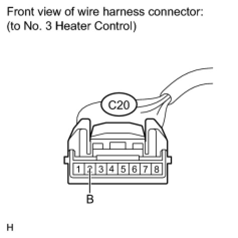
(b) Measure the voltage according to the value(s) in the table below.
Standard voltage:

(c) Reconnect the No. 3 heater control connector.
NG -- REPAIR OR REPLACE HARNESS OR CONNECTOR
OK -- Continue to next step.
4. CHECK HARNESS AND CONNECTOR (NO. 3 HEATER CONTROL - A/C AMPLIFIER)
(a) Disconnect the C20 No. 3 heater control connector.

(b) Disconnect the C8 A/C amplifier connector.
(c) Measure the resistance according to the value(s) in the table below.
Standard resistance:

(d) Reconnect the No. 3 heater control connector.
(e) Reconnect the A/C amplifier connector.
NG -- REPAIR OR REPLACE HARNESS OR CONNECTOR
OK -- PROCEED TO NEXT CIRCUIT INSPECTION SHOWN IN PROBLEM SYMPTOMS TABLE