Part 1
2AZ-FE ENGINE MECHANICAL: ENGINE UNIT: REASSEMBLY
HINT
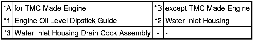
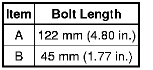
Check whether the engine is TMC made or not by referring to the following illustration.

Text in Illustration
1. INSTALL NO. 1 BALANCE SHAFT BEARING
(a) Align the bearing claw with the claw groove, and push in the 8 bearings.

NOTICE:
Do not apply engine oil to the contact surfaces of the balance shaft bearing and balance shaft housing.
Text in Illustration
(b) Apply a light coat of the engine oil to the bearings.
2. INSTALL NO. 1 AND NO. 2 BALANCE SHAFTS
(a) Rotate the No. 1 driven gear of the No. 1 balance shaft in the rotating direction until it hits the stopper.
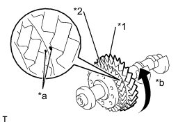
Text in Illustration
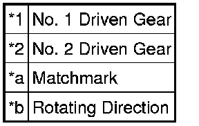
(b) Confirm that the matchmarks on the No. 1 and No. 2 driven gears are aligned.
(c) Confirm that the alignment marks on the No. 1 and No. 2 balance shafts are aligned.
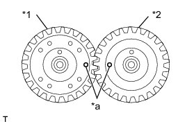
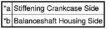
Text in Illustration
(d) Align the alignment marks on the No. 1 and No. 2 balance shafts as shown in the illustration.
Text in Illustration
(e) Place the No. 1 and No. 2 balance shafts onto the crankcase.
(f) Apply a light coat of engine oil to the threads and under the heads of the bolts.
(g) Using several steps, uniformly install and tighten the 8 bolts in the sequence shown in the illustration.
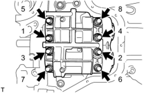
Torque : 22 Nm (220 kgf-cm, 16 ft-lbf)
(h) Mark the front of the bolts with paint.
Text in Illustration
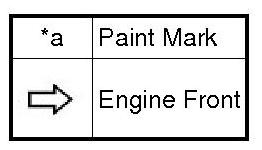
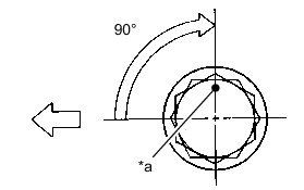
(i) Further tighten the bolts by 90° as shown in the illustration.
(j) Check that the paint mark is now at a 90° angle to the front.
3. INSTALL STIFFENING CRANKCASE ASSEMBLY
(a) Remove any old packing material and be careful not to drop any oil on the contact surfaces of the cylinder block and crankcase.
(b) Place a new O-ring on the cylinder block as shown in the illustration.
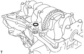
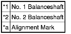
(c) With the No. 1 crank pin of the crankshaft placed at the 6 o'clock position, install the No. 1 and No. 2 balance shafts and align the adjusting holes as shown in the illustration.
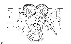
Text in Illustration
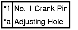
(d) Apply a continuous bead of seal packing (Diameter 2.5 to 3.0 mm (0.098 to 0.118 in.)) as shown in the illustration.
Seal Packing:
Toyota Genuine Seal Packing Black, Three Bond 1207B or equivalent
NOTICE:
* Remove any oil from the contact surface.
* Install the crankcase within 3 minutes of applying seal packing.
* Do not add engine oil for at least 2 hours after installing the crankcase.
Text in Illustration

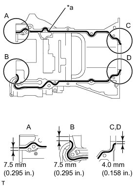
(e) Temporarily install the crankcase with the 11 bolts.
(f) Uniformly tighten the bolts.
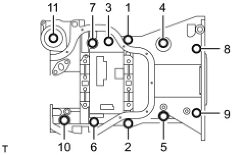
Torque : 24 Nm (245 kgf-cm, 18 ft-lbf)
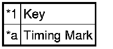
(g) Confirm that the timing marks on the balance shafts are aligned when the key groove the is placed at the 6 o'clock position, as shown in the illustration.
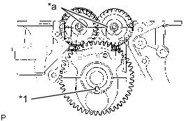
Text in Illustration
4. INSTALL OIL PUMP ASSEMBLY Installation
5. INSTALL REAR CRANKSHAFT OIL SEAL Installation
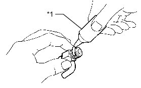
6. INSTALL NO. 1 TAPER HEAD SCREW PLUG
(a) Apply adhesive to 2 or 3 threads of the plug, and install it.

Torque : 26 Nm (265 kgf-cm, 19 ft-lbf)
Adhesive:
Toyota Genuine Adhesive 1324, Three Bond 1324 or equivalent
NOTICE:
* Install the plug within 3 minutes of applying adhesive.
* Do not add coolant for at least an hour after installing the plug.
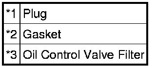
7. INSTALL OIL CONTROL VALVE FILTER
(a) Check that there are no foreign objects on the mesh part of the oil control valve filter.
(b) Using a 8 mm socket hexagon wrench, install a new gasket and the oil control valve filter with the plug.

Torque : 30 Nm (306 kgf-cm, 22 ft-lbf)
Text in Illustration
8. INSTALL INLET WATER HOUSING (except TMC Made Engine)

(a) Install the 2 new O-rings onto the inlet water housing.
(b) Using several steps, uniformly install and tighten the 5 bolts in the sequence shown in the illustration.
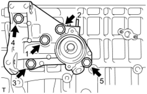
Torque : 35 Nm (357 kgf-cm, 26 ft-lbf)
(c) Using E5 "TORX" socket wrench, remove the 6 stud bolts from the inlet water housing.
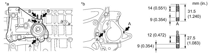
Text in Illustration

Torque : 5.0 Nm (51 kgf-cm, 44 in-lbf)
9. INSTALL INLET WATER HOUSING DRAIN COCK ASSEMBLY (except TMC Made Engine)
(a) Apply adhesive to 2 or 3 threads of the drain cock.
Adhesive:
Toyota Genuine Adhesive 1344, Three Bond 1344 or equivalent
Text in Illustration

(b) After tightening the drain cock to the specified torque, further tighten it one turn or less to set the drain cock pipe as specified in the illustration.
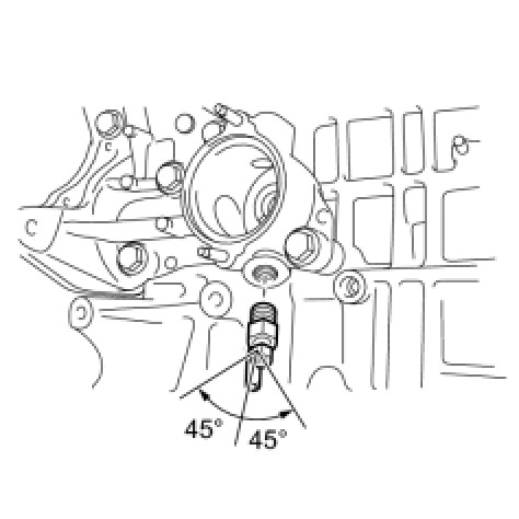
Torque : 25 Nm (255 kgf-cm, 18 ft-lbf)
NOTICE:
* Install the drain cock within 3 minutes of applying adhesive.
* Do not add coolant for at least an hour after installing the drain cock.
* Do not turn the drain cock by more than 1 revolution (360°) after tightening the drain cock to the specified torque.
* Do not loosen the drain cock after setting it correctly.
(c) Install the plug onto the water drain cock.
Torque : 13 Nm (133 kgf-cm, 10 ft-lbf)
10. INSTALL CYLINDER BLOCK WATER JACKET SPACER (for TMC Made Engine)
(a) Install the cylinder block water jacket spacer into the cylinder block as shown in the illustration.
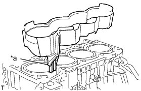
HINT
Be sure to face the slope to the front of the engine.
Text in Illustration