Drive Pinion Shaft Assembly
A: REMOVAL1. Remove the manual transmission assembly from vehicle.
2. Remove the transfer case with extension case assembly.
3. Remove transmission case.
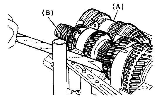
4. Remove the drive pinion shaft assembly.
NOTE: Use a hammer handle, etc. to remove if too tight.
B: INSTALLATION
1. Remove the differential assembly.

2. Alignment marks/numbers on hypoid gear set
The upper number on driven pinion is the match number for combining it with hypoid driven gear. The lower number is the margin of error used for matchin. If no lower number is shown, the value is zero. The number on hypoid driven gear indicates a number for combination with drive pinion
3. Place the drive pinion shaft assembly on right hand transmission main case without shim and tighten the bearing mounting bolts.

4. Inspection and adjustment of ST
NOTE:
^ Loosen the two bolts and adjust so that the scale indicates 0.5 correctly when the plate end and the scale end are on the same level.
^ Tighten the two bolts.
ST 499917500 DRIVE PINION GAUGE ASSY
5. Position the ST by inserting the knock pin of ST into the knock hole in the transmission case.
ST 499917500 DRIVE PINION GAUGE ASSY

6. Slide the drive pinion gauge scale with finger tip and read the value at the point where it matches with the end face of drive pinion.
ST 499917500 DRIVE PINION GAUGE ASSY
7. The thickness of shim shall be determined by adding the value indicated on drive pinion to the value indicated on the ST. (Add if the number on drive pinion is prefixed by + and subtract if the number is prefixed by -.)
ST 499917500 DRIVE PINION GAUGE ASSY

8. Select one to three shims from the next table for the value determined as described above and take a shim thickness, which is closest to the said value.
9. Install the differential assembly.
10. Set the transmission main shaft assembly and drive pinion assembly in position. (So there is no clearance between the two when moved all the way to the front). Inspect the suitable 1st-2nd, 3rd- 4th and 5th shifter fork so that the coupling sleeve and reverse driven gear are positioned in the center of their synchronizing mechanisms.
11. Install the transmission case.
12. Install the transfer case with extension case assembly.
13. Install the manual transmission assembly to vehicle.
C: DISASSEMBLY
CAUTION: Attach a cloth to the end of driven shaft (on the frictional side of thrust needle bearing) during disassembly or reassembly to prevent damage.

1. Straighten the lock nut at staked portion. Remove the lock nut using ST1, ST2 and ST3.
ST1 899884100 HOLDER
ST2 498427100 STOPPER
ST3 899988608 SOCKET WRENCH (27)

2. Withdraw the drive pinion from driven shaft. Remove the differential bevel gear sleeve, adjusting washer No. 1, adjusting washer No. 2, thrust bearing, needle bearing, drive pinion collar, needle bearing and thrust bearing.

3. Remove the roller bearing and washer using ST and press.
CAUTION: Do not reuse roller bearing.
ST 498077000 REMOVER

4. Straighten the lock nut at staked portion. Remove the lock nut using ST1 and ST2.
ST1 499987300 SOCKET WRENCH (50)
ST2 899884100 HOLDER

5. Remove the 5th driven gear using ST.
ST 499857000 5TH DRIVEN GEAR REMOVER
6. Remove the woodruff key.

7. Remove the roller bearing, 3rd-4th driven gear using ST1 and ST2.
ST1 499757002 INSTALLER
ST2 899714110 REMOVER
8. Remove the key.

9. Remove the 2nd driven gear, inner baulk ring, synchro cone and outer baulk ring.

10. Remove the 1st driven gear, 2nd gear bushing, gear and hub using ST1 and ST2.
NOTE: Replace the gear and hub if necessary. Do not attempt to disassemble if at all possible because they must engage at a specified point. If they have to be disassembled, mark the engaging point beforehand.
ST1 499757002 INSTALLER
ST2 899714110 REMOVER
11. Remove the sub gear for 1st driven gear.
D: ASSEMBLY

1. Install the sleeve and assembly by matching alignment marks.
NOTE:
^ Use the new gear and hub assembly, if the gear or hub have been replaced.
2. Install the washer, snap ring and sub gear to 1st driven gear.
3. Install the 1st driven gear, 1st baulk ring, gear and hub assembly onto driven shaft.
NOTE:
^ Take care to install gear and hub assembly in proper direction.
^ Align the baulk ring and gear & hub assembly with key groove.

4. Install the 2nd driven gear bushing onto driven shaft using ST1, ST2 and press.
CAUTION:
^ Attach a cloth to the end of driven shaft to prevent damage.
^ Do not apply pressure in excess of 10 kN (1 ton, 1.1 US ton, 1.0 Imp ton).
NOTE: When press fitting, align the oil holes of shaft and bush.
ST1 499277200 INSTALLER
ST2 499587000 INSTALLER
5. Install the 2nd driven gear, inner baulk ring, synchro cone, outer baulk ring and insert onto driven shaft.

6. After installing key on driven shaft, install the 3rd-4th driven gear using ST and press.
CAUTION: Do not apply pressure in excess of 10 kN (1 ton, 1.1 US ton, 1.0 Imp ton).
NOTE: Align the groove in baulk ring with insert.
ST4 99277200 INSTALLER

7. Install a set of roller bearings onto the driven shaft using ST and press.
CAUTION: Do not apply pressure in excess of 10 kN (1 ton, 1.1 US ton, 1.0 Imp ton).
ST 499277200 INSTALLER

8. Position the woodruff key in groove on the rear of driven shaft. Install 5th driven gear onto drive shaft using ST and press.
CAUTION: Do not apply pressure in excess of 10 kN (1 ton, 1.1 US ton, 1.0 Imp ton).
ST 499277200 INSTALLER

9. Install the lock washer. Install lock nut and tighten to the specified torque using ST.
ST 499987300 SOCKET WRENCH (50)
Tightening torque: 265 Nm (27 kgf-cm, 195 ft. lbs.)

NOTE:
^ Stake the lock nut at two points.
^ Using spring balancer, check that starting torque of roller bearing is 0.1 to 1.5 N (0.01 to 0.15 kgf, 0.02 to 0.33 ft).

10. Install the roller bearing onto drive pinion.
NOTE: When installing roller bearing, note its directions (front and rear) because the knock pin hole in outer race is offset.

11. Install the washer using ST1, ST2 and press.
CAUTION:
^ Discard old lock nuts, replace with new ones.
^ Secure lock nut in four places.
ST1 499277100 BUSH 1-2 INSTALLER
ST2 499277200 INSTALLER

12. Install the thrust bearing and needle bearing. Install the driven shaft assembly.

13. Install the drive pinion collar, needle bearing, adjusting washer No. 2, thrust bearing, adjusting washer No. 1 and differential bevel gear sleeve in that order.
NOTE: Be careful because the spacer must be installed in proper direction.
E: INSPECTION
Disassembled parts should be washed clean first and then inspected carefully.

1. Bearings
Replace bearings in the following cases:
^ Bearings, whose balls, outer races and inner races are broken or rusty.
^ Worn bearings
^ Bearings that fail to turn smoothly or make abnormal noise when turned after gear oil lubrication.
^ The ball bearing on the rear side of the drive pinion shaft should be checked for smooth rotation before the drive pinion assembly is disassembled. In this case, because a preload is working on the bearing, its rotation feels like it is slightly dragging unlike the other bearings.
^ Bearings having other defects
2. Bushing (each gear)
Replace the bushing in the following cases:
^ When the sliding surface is damaged or abnormally worn.
^ When the inner wall is abnormally worn.
3. Gears
^ Replace gears with new ones if their tooth surfaces are broken, damaged, or excessively worn.
^ Correct or replace if the cone that contacts the baulk ring is rough or damaged.
^ Correct or replace if the inner surface or end face is damaged.

4. Baulk ring Replace the ring in the following cases:
^ When the inner surface and end face are damaged.
^ When the ring inner surface is abnormally or partially worn down.
^ If the gap between the end faces of the ring and the gear splined part, is excessively small when the ring is pressed against the cone.
Clearance (A): 0.5 - 1.0 mm (0.020 - 0.040 inch)
^ When the contact surface of the synchronizer ring insert is scored or abnormally worn down.

5. Shifting insert key
Replace the insert if deformed, excessively worn, or defective in any way.
6. Oil seal
Replace the oil seal if the lip is deformed, hardened, damaged, worn, or defective in any way.
7. O-ring
Replace the O-ring if the sealing face is deformed, hardened, damaged, worn, or defective in any way.
F: ADJUSTMENT
1. THRUST BEARING PRELOAD

1. After completing the preceding steps 1) through 3), select adjusting washer No. 1 so that the dimension (H) is zero through visual check. Position washer (18.3 x 30 x 4) and lock washer (18 x 30 x 2) and install lock nut (18 x 13.5).

2. Using ST1, ST2 and ST3, tighten the lock nut to the specified torque.
ST1 899884100 HOLDER
ST2 498427100 STOPPER
ST3 899988608 SOCKET WRENCH (27)
Tightening torque: 118 Nm (12 kgf-cm, 86.8 ft. lbs.)

3. After removing ST2, measure the starting torque using torque driver.
ST1 899884100 HOLDER
ST3 899988608 SOCKET WRENCH (27)
Starting torque: 0.3 - 0.8 Nm (0.03 - 0.08 kgf-cm, 0.2 - 0.6 ft. lbs.)


4. If starting torque is not within specified limit, select new adjusting washer No. 1 and recheck starting torque.


5. If specified starting torque range cannot be obtained when a No. 1 adjusting washer is used, then select a suitable No. 2 adjusting washer from those listed in the following table. Repeat steps 1) through 4) to adjust starting torque.
6. Recheck that the starting torque is within specified range, then clinch the lock nut at four positions.