Assembly
ASSEMBLY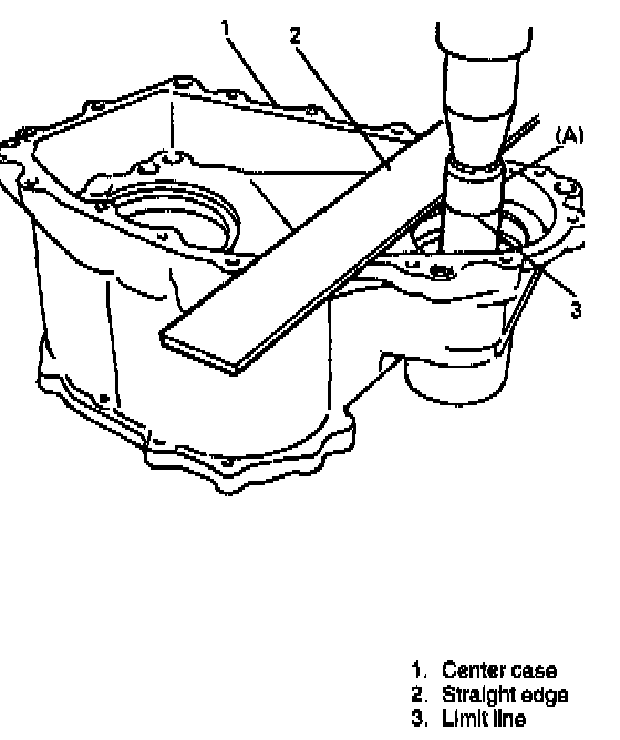
1. Using press and special tool, press-fit needle bearing into center case. As shown in figure, apply straightedge to top surface of case and press-fit till limit line of special tool aligns with bottom surface of straightedge (i.e., case surface).
NOTE:
^ Press-fitting needle bearing according to above procedure will set needle bearing 3 mm before it hits case bottom.
^ Once it is press-fit all way down to case bottom, removal would be very difficult if it becomes necessary.
Special Tool
(A): 09951 -76010
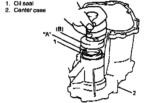
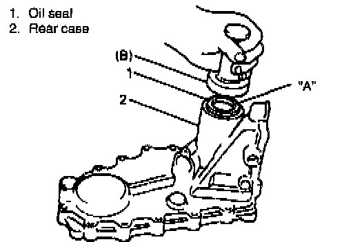
2. Using special tool and hammer, drive oil seal into center case until it becomes flush with case surface. Apply grease to oil seal lip.
"A": Grease 99000-25010
Special Tool
(B): 09913-75520
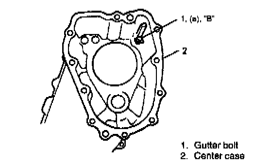
3. Install oil gutter and tighten bolt applying thread lock cement.
Tightening Torque
(a): 8 Nm (0.8 kg-m, 5.5 ft. lbs.)
"B": Cement 99000-32020
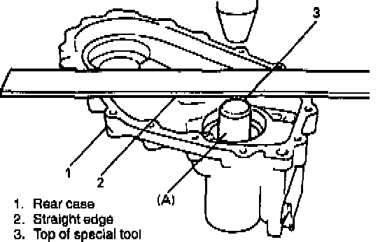
4. Using special tool and press, install needle bearing into rear case. As shown in figure, apply straightedge to case surface and press-fit till top of special tool aligns with bottom surface of straightedge (i.e., case surface).
NOTE: As with needle bearing in center case, above installation procedure will set needle bearing at a position 3 mm before it hits case bottom.
Special Tool
(A): 09951-76010
5. Using special tool and hammer, install oil seal into rear case until it becomes flush with case surface. Apply grease to oil seal lip.
"A": Grease 99000-25010
Special Tool
(B): 09913-75520
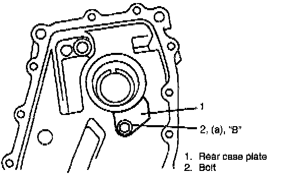
6. Install rear case plate and bolt applying thread lock cement.
NOTE: Removal of rear case plate is not required normally. However, if it is removed or replaced, install it with bolt applied with thread lock cement.
"B": Cement 99000-32020
Tightening Torque
(a): 8 Nm (0.8 kg-m, 5.5 ft. lbs.)
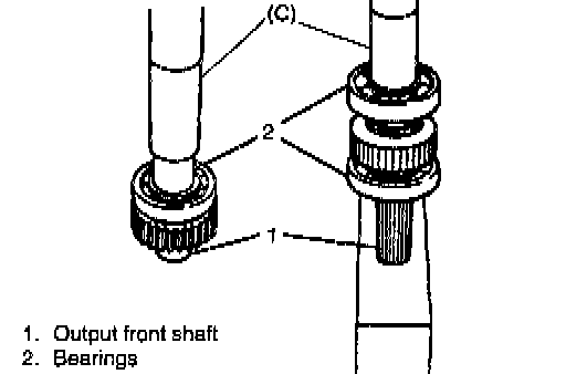
7. Using press and special tools, install bearings to front shaft. Bearings for both front and rear are identical.
Special Tool
(C): 09913-84510
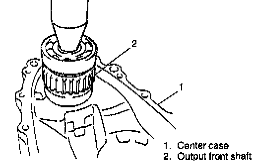
8. Using press, drive output front shaft assembly into center case.
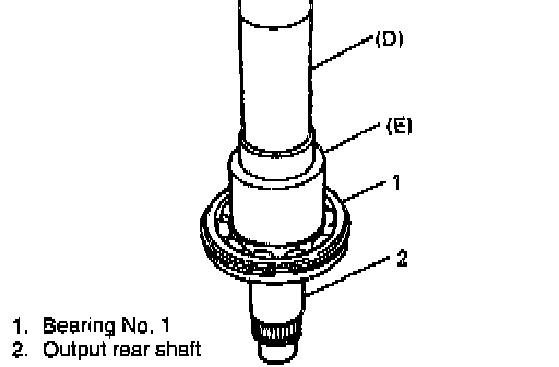
9. Using press and special tools, install bearing No. 1 into output rear shaft. Place circlip portion of bearing on top as shown in figure re.
Special Tool
(D): 09925-18010
(E): 09940-53111
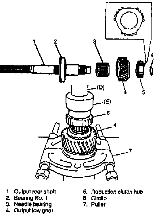
10. Install needle bearing and output low gear and then press-fit reduction clutch hub onto output rear shaft by using press and special tool and secure them with circlip. Hub has specific installing direction.
Special Tool
(D): 09925-18010
(E): 09940-53111
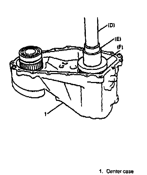
11. Combine special tools and press-fit output rear shaft assembly into center case.
NOTE Use special tool (F) with its under-cut side faced down (toward bearing).
Special Tool
(D): 09925-18010
(E): 09940-53111
(F): 09951-26010
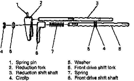
12. Install fork to corresponding shift shaft.
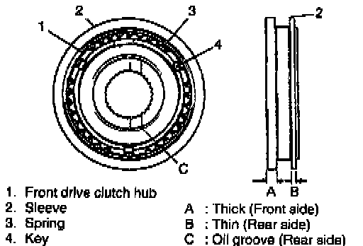
13. Fit sleeve to front drive clutch hub, place 3 synchronizer keys in it and then set synchronizer springs. When installing, note that front drive clutch hub and sleeve have specific installing direction.
NOTE: Make sure that bent end of synchronizer spring is inserted into hole.
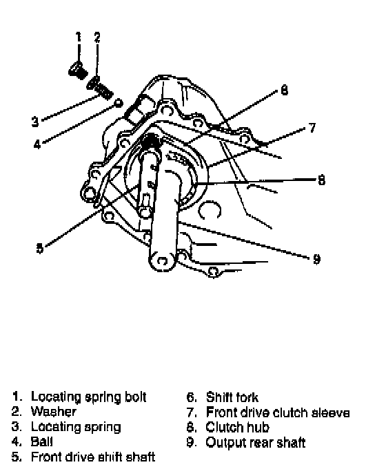
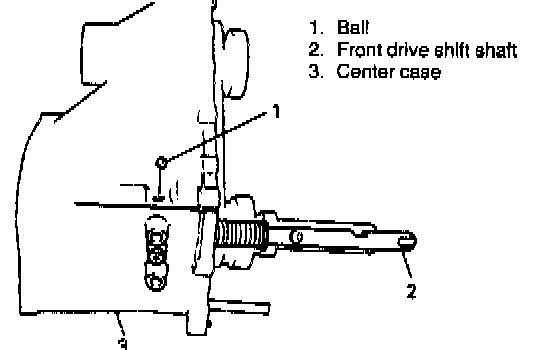
14. Install front drive fork shaft assembly and sleeve& hub together into center case all at once. Then put locating ball and spring also into case and loosely install bolt.
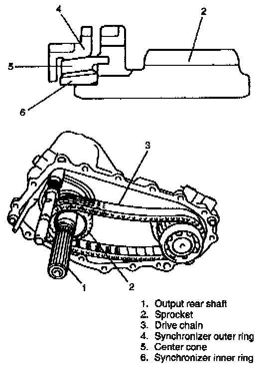
15. With the outer ring, the cone and the inner ring put together and installed to the sprocket gear as shown in figure, install them together with the chain to the output rear shaft.
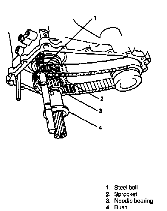
16. Install needle bearing and bush to sprocket.
Also install steel ball, using care not to drop it.
NOTE:
^ Point mark on output rear shaft between positions of bearing No. 2 and speedometer drive gear indicates steel ball location in the front.
^ Point mark on bush flange also means position where steel ball is met.
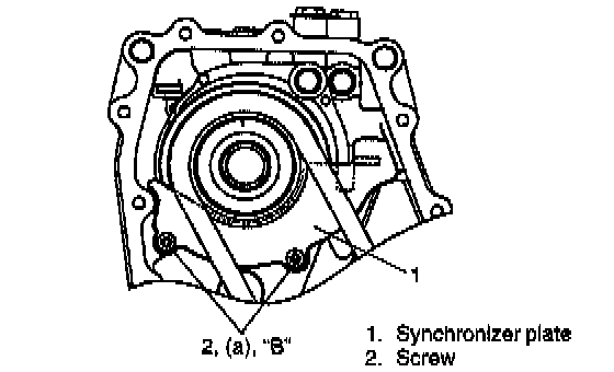
17. Install synchronizer plate.
Tightening Torque
(a): 10 Nm (1.0 kg-m, 7.5 ft. lbs.)
"B": Cement 99000-32020
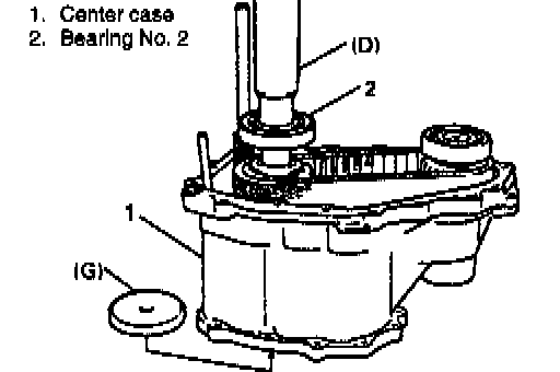
18. Using special tool, press-fit bearing No. 2 into output rear shaft.
It is necessary to place support base at lower end of shaft.
Special Tool
(D): 09925-18010
(G): 09926-68310
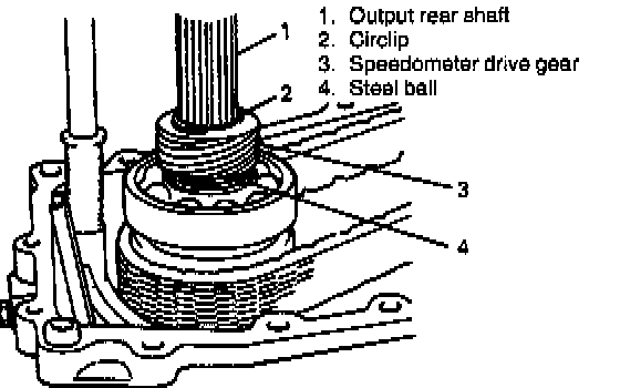
19. After installing large size circlip, install speedometer drive gear and secure it with small size circlip.
20. Install interlock steel ball.
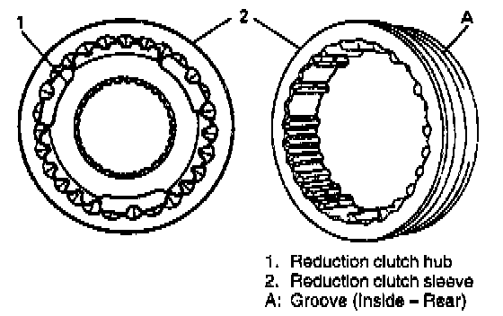
21. Fit sleeve to reduction clutch hub.
NOTE:
^ Sleeve used here is identified by tapered splines which make it different from front drive clutch sleeve.
^ Circumferential groove mark (thicker rail side which works as shift stopper) should be inside (rear).
^ Hub has no specific direction.
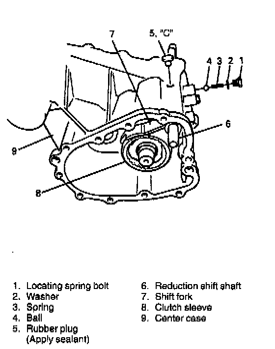
22. Combine sleeve & hub to reduction shift shaft assembly and install them into center case. Then put locating ball and spring also into case and loosely install bolt.
23. With sealant applied to rubber plug, insert it into hole in case.
NOTE: When installing reduction shift shaft, front drive shift shaft must be placed at 4WD position.
"C": Sealant 99000-31110
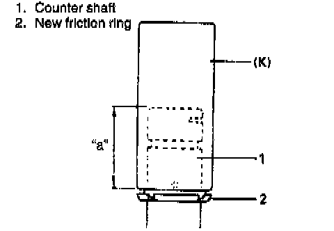
24. If friction ring has been removed from counter shaft, press-fit new one onto shaft, using care so that it is installed in proper direction and position as shown in figure.
Special Tool
(K): 09913-80112
Installing position "a": 39.5 mm (1.56 inch)
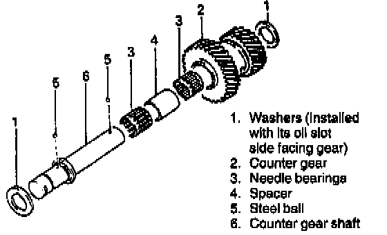
25. Install needle bearing, spacer, counter gear, steel balls and washers onto shaft.
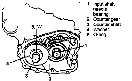
26. Install counter shaft assembly into case. If O-ring has been removed, install new O-ring onto shaft and apply grease. Also, install low gear needle bearing.
"A": Grease 99000-25010
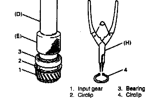
27. With circlip placed on input gear, press-fit input gear bearing.
28. Fix bearing with circlip.
Special Tool
(D): 09925-18010
(E): 09940-53111
(H): 09900-06107
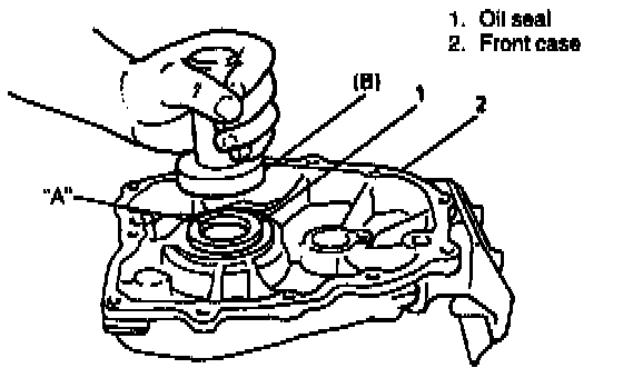
29. Install oil seal to front case so that end surface of oil seal becomes flush with that case. Apply grease to oil seal lip.
"A": Grease 99000-25010
Special Tool
(B): 09913-75520
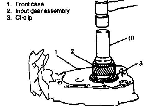
30. Using special tool, drive input gear assembly into front case.
Special Tool
(i): 09951-16080
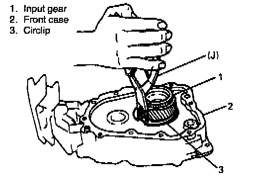
31. Fix with circlip by means of snap ring pliers.
Special Tool
(J): 09900-06108
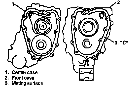
32. Oil to rotating parts and clean mating surfaces of both center and front cases.
33. Apply sealant to mating surface of front case evenly and put cases together.
NOTE:
^ For smooth installation of front case, apply grease to counter shaft 0-ring.
^ When mating front case, make sure that input gear meshes with counter gear first.
"C": Sealant 99000-31110
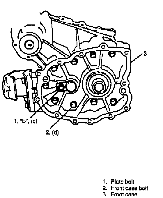
34. Torque 9 front case bolts to specification.
35. Torque counter shaft plate fixing bolt applied with thread lock cement to specification.
NOTE:
^ After tightening bolts, check input gear and output rear shaft for smooth rotation by hand at low and high speed position.
^ Also check front drive shift for proper operation.
"B": Cement 99000-32020
Tightening Torque
(c): 23 Nm (2.3 kg-m, 17.0 ft. lbs.)
(d): 23 Nm (2.3 kg-m, 17.0 ft. lbs.)
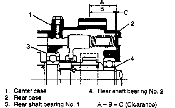
36. Before assembling rear case, shim adjustment is required.
Follow steps described below.
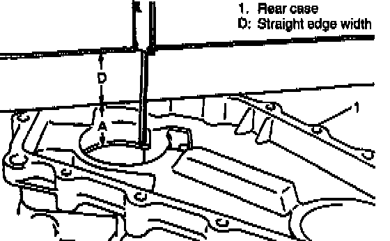
1. Measure rear case dimension A (from mating surface to bearing bore bottom) by using straightedge and vernier caliper. Width of straightedge D plus A is obtained.
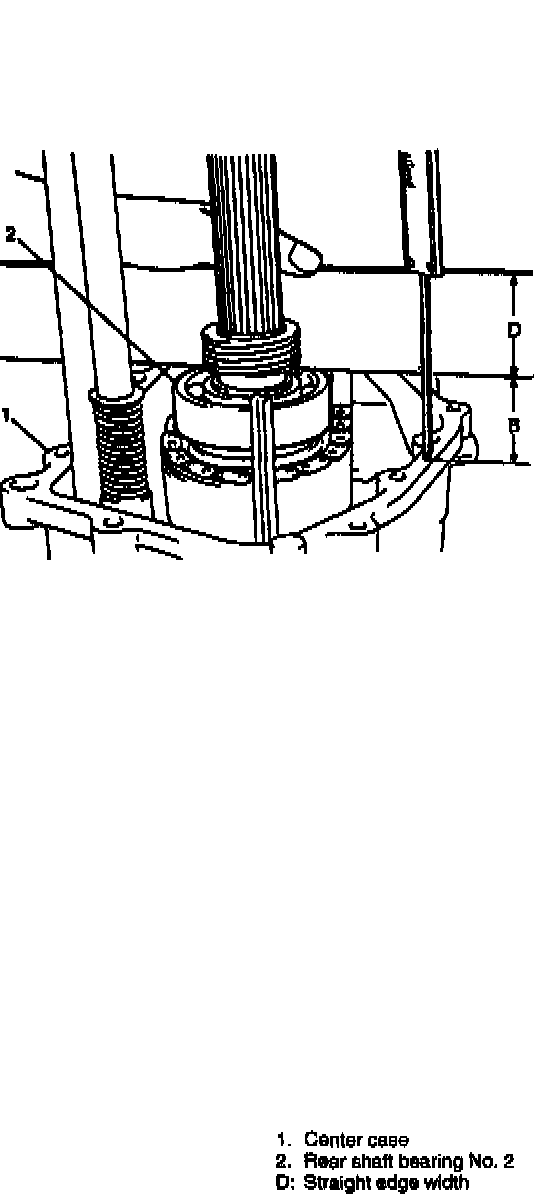
2. Place straightedge on bearing No. 2 securely and measure bearing height B (from center case mating surface to No. 2 bearing top).
CAUTION: Bridging straightedge between No. 2 bearing and output front shaft bearing brings misreading.
3. Obtain clearance C in following calculation.
C = (A + D) - (B + D)
4. Select a shim from among following available sizes and install it in bearing bore of rear case.
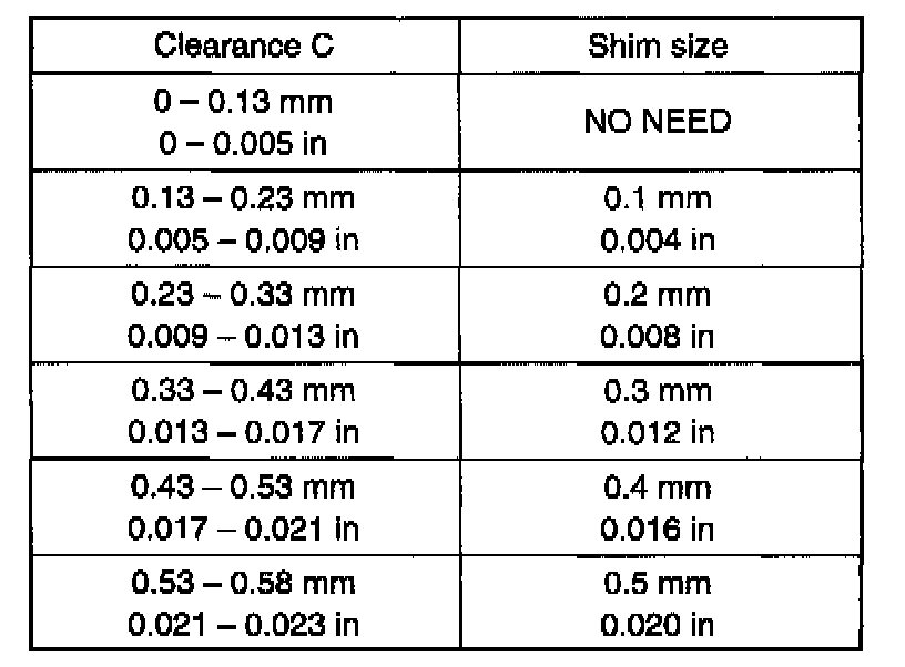
CAUTION: Installing of over sized shim beyond specification in the following table may cause tight rotation of rear shaft and consequential bearing damage.
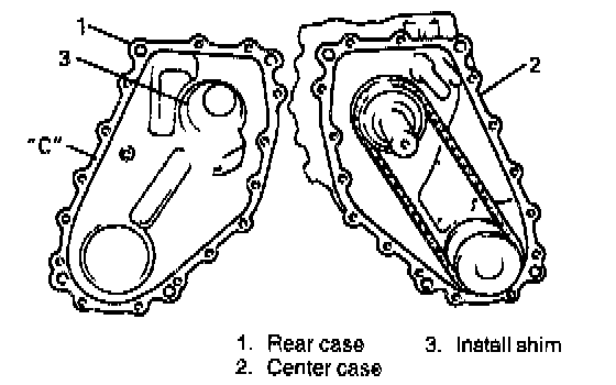
37. Clean mating surfaces of both center and rear cases again, apply sealant to mating surface of rear case, and put them together.
"C": Sealant 99000-31110
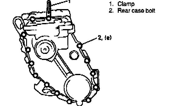
38. Torque 15 rear case bolts to specification.
NOTE: After tightening bolts, provisionally install universal joint flange into rear shaft and check to make sure smooth rotation of shaft.
Tightening Torque
(e): 23 Nm (2.3 kg-m 17.0 ft. lbs.)
39. [For transfer for TYPE 2 manual transmission]
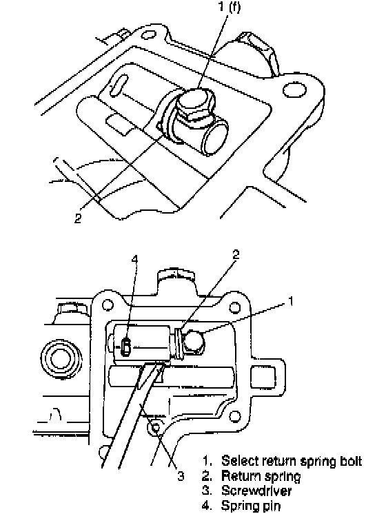
1. With reduction shift shaft shifted to high speed side, fit yoke to shaft and install return spring as shown in figure. Tighten bolt to specified torque.
Tightening Torque
(f): 5.5 Nm (0.55 kg-m. 4.0 ft. lbs.)
2. Fix reduction shift yoke with spring pin while aligning shift yoke with shift shaft as shown in figure.
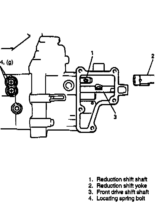
39. [For transfer for A/T and TYPE 1 manual transmission)
With reduction shift shaft shifted to left (at high speed side) as shown in figure, fit yoke to shaft and fix it with spring pin.
NOTE: Be careful not to let spring pin fall off.
40. Torque locating spring bolts of shifters to specification.
Tightening Torque
(g): 26 Nm (2.6 kg-m, 19.0 ft. lbs.)
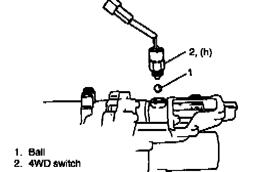
41. Install steel balls and 4WD/4WD-LOW switches.
Tightening Torque
(h): 20 Nm (2.0 kg-m, 14.5 ft. lbs.)
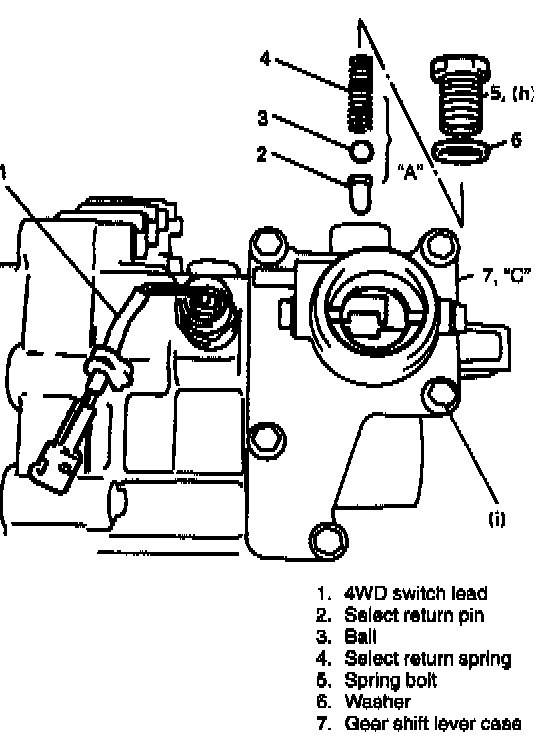
42. Fix lead of 4WD switch with clamp.
43. Apply grease to select return system parts and install them.
Then torque select return spring bolt to specification (For transfer with A/T or TYPE 1 manual transmission only).
"A": Grease 99000-25010
44. Clean mating surfaces of both gear shift lever case and rear case, and with sealant applied to mating surface of gear shift lever case, push both cases together.
"C": Sealant 99000-31110
45. Torque gear shift lever case bolts to specification.
Tightening Torque
(h): 35 Nm (3.5 kg-m, 25.5 ft. lbs.)
(i): 13 Nm (1.3 kg-m, 9.5 ft. lbs.)
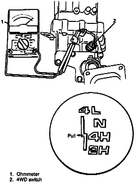
46. Install gear shift control lever temporarily and check to make sure that it shifts to each shift position smoothly. Also check shaft for rotation.
47. Confirm 4WD switch has turned ON at 4WD position (4H and 4L).
48. Confirm 4WD low switch has turned ON at 4WD low and Neutral position.
49. Upon completion of above checks, remove shift control lever.