Disassembly
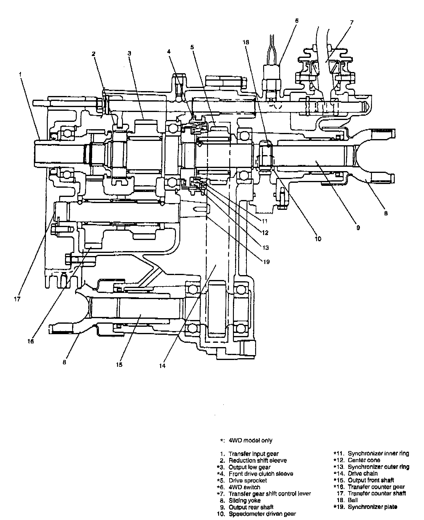

UNIT REPAIR
DISASSEMBLY
1. Remove 4WD switch and take out steel ball.
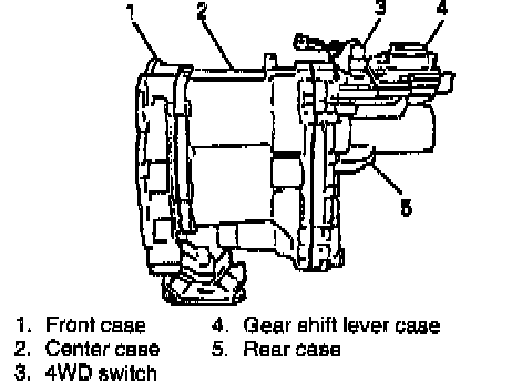
2. Remove 5 bolts and then remove gear shift lever case.
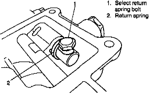
3. [For transfer for A/T and TYPE 1 manual transmission]
After removing bolt of select return system, take out spring, steel ball and pin.
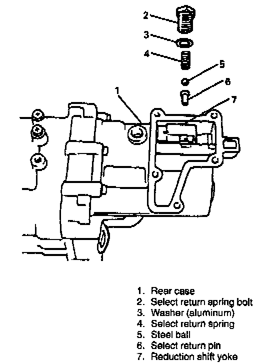
3. [For transfer for TYPE 2 manual transmission]
Remove select return spring bolt and then return spring.
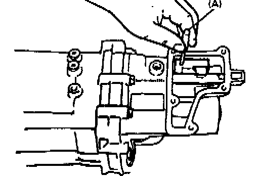
4. By hammering special tool, drive spring pin out of reduction shift yoke.
NOTE:
^ Pin may drop into case when driven out. Therefore, take it out when case is disassembled.
^ After spring pin is removed, yoke may be either taken out.
Special Tool
(A): 09922-85811
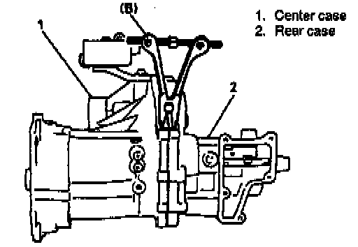
5. Remove 15 rear case bolts and then separate case by using special tool.
NOTE: To separate case, use special tool at 4 points in turn and make opening wider evenly.
Special Tool
(B): 09912-34510
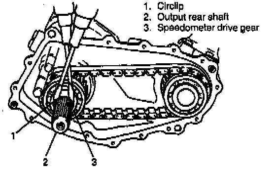
6. Remove circlip by using screwdrivers and hammer, then pull out speedometer drive gear and steel ball.
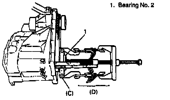
7. Remove circlip for bearing and pull out bearing No. 2 by combination of special tools.
Special Tool
(C): 09921-57810
(D): 09927-18411
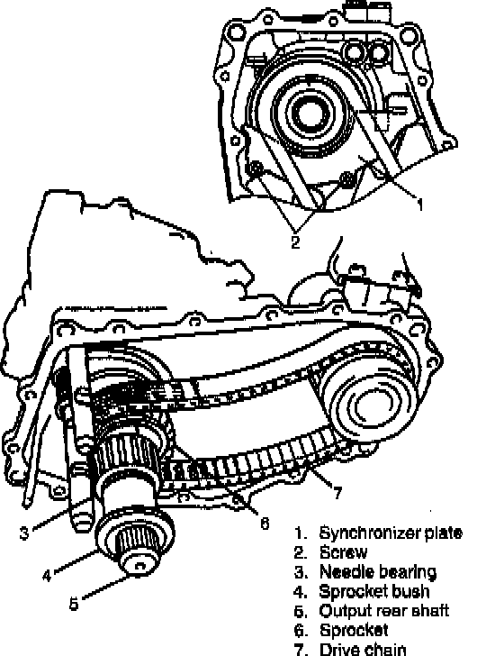
8. Remove synchronizer plate screws and pull out sprocket bush and needle bearing from output rear shaft.
9. Remove sprocket with drive chain and synchronizer plate.
NOTE: Watch out for steel ball which comes off from shaft when bush is pulled out so as not to lose it.
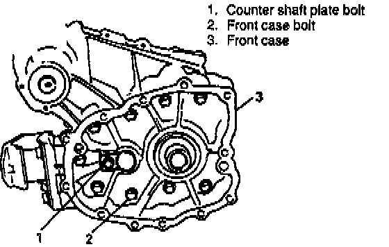
10. Remove counter shaft plate bolt from front case, and counter shaft plate will come off.
11. Remove front case by removing its 9 bolts.
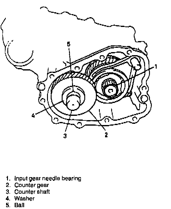
12. Remove input gear needle bearing. Remove counter gear shaft together with needle bearings, spacer, washers and steel balls from case.
NOTE:
^ Watch out for steel balls which come out from between shaft and washers (front and rear) so as not to lose them.
^ Check friction ring lip for damage and wear. Replace if necessary.
^ Neither 0-ring nor friction ring should be removed unless absolutely necessary.
If removed, use new parts for reinstallation. Removed ones should not be reused.
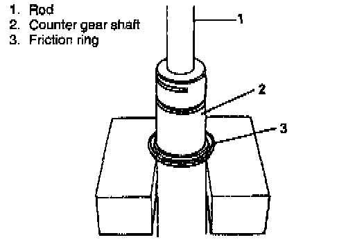
13. Remove 0-ring from shaft and then remove friction ring from shaft, using a proper size rod and press.
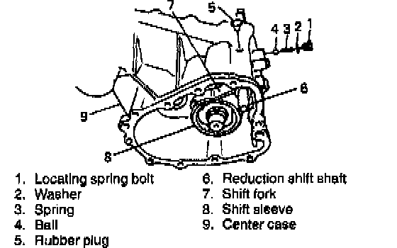
14. Remove locating spring bolt with washer, spring and ball for reduction shift. Remove rubber plug as well.
15. Pull out reduction shift shaft together with fork and sleeve.
NOTE: For this removal, be sure to place front drive fork shaft at 4WD position.
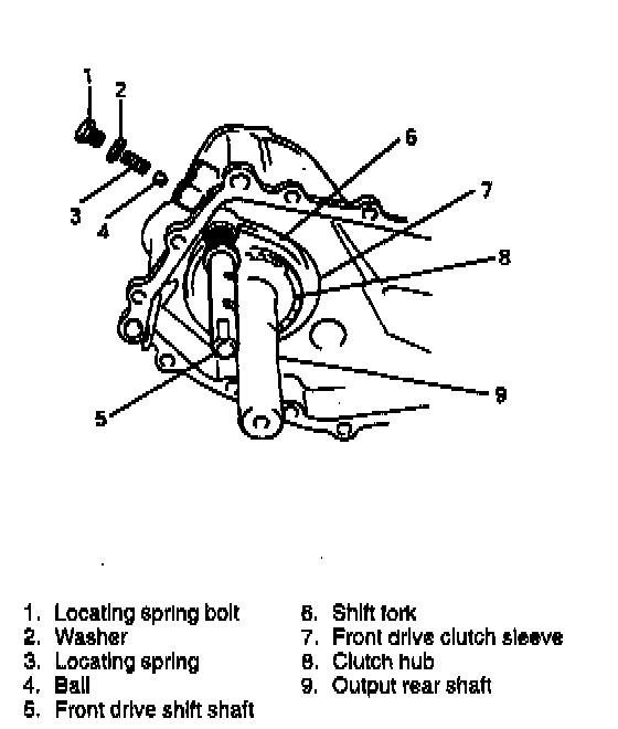
16. Remove locating spring bolt with washer, spring and ball for front drive shift.
17. Pull out front drive shift fork& shaft, sleeve and hub all together.
NOTE: Watch out for interlock steel ball which comes out from between 2 shift shafts so as not to lose it. If it doesn't come out, remove rubber plug and take it out.
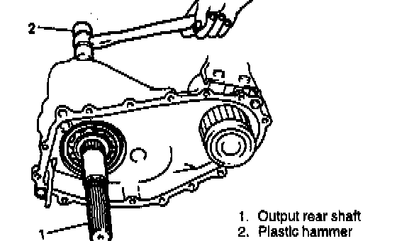
18. Using plastic hammer, drive out output rear shaft assembly with bearing. Output low gear and reduction clutch hub also come off as they are installed to shaft.
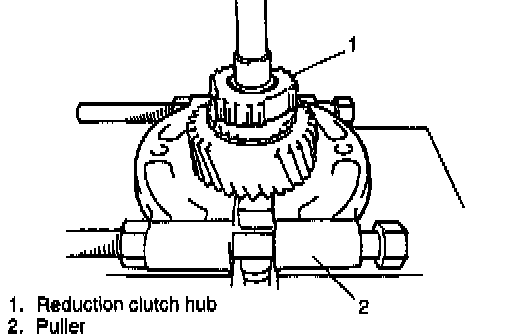
19. Pull off circlip from output rear shaft and remove reduction clutch hub by using puller and press. Then pull out output low gear and needle bearing.
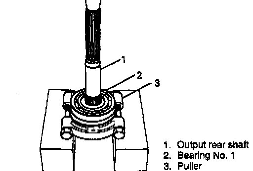
20. Using puller and press, remove bearing No. 1 from shaft.
21. Remove oil seal from center case.
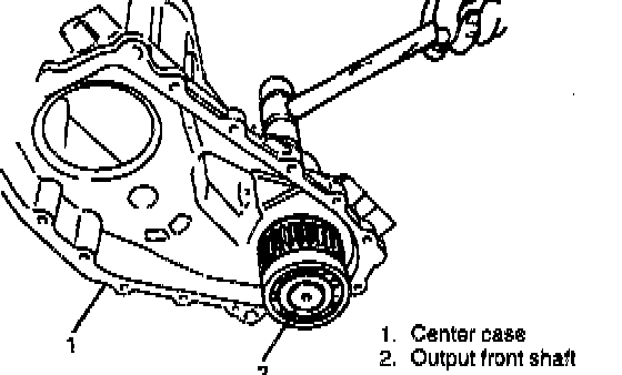
22. Using plastic hammer, drive out output front shaft together with bearings.
CAUTION: If oil seal remains in center case, be careful not to damage oil seal by hitting. Use drive punch for hammering.
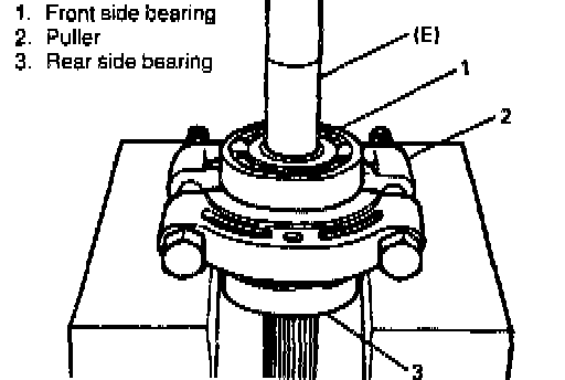
23. Take off bearings from shaft by using press and puller. Removal of front side bearing requires special tool additionally as shown.
Special Tool
(E): 09925-98221
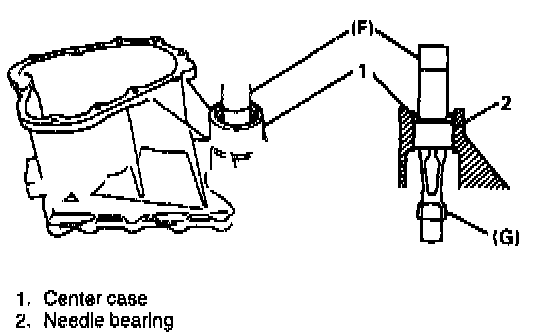
24. To remove needle bearing from center case, combine special tools as shown in figure and press them.
Special Tool
(F): 09913-84510
(G): 09941-64511
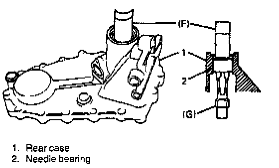
25. Remove oil seal from rear case. And then, using same special tools and press as in above step, remove needle bearing from rear case.
CAUTION: Be careful not to damage oil seal, if it remains in rear case.
Special Tool
(F): 09913-84510
(G): 09941-64511
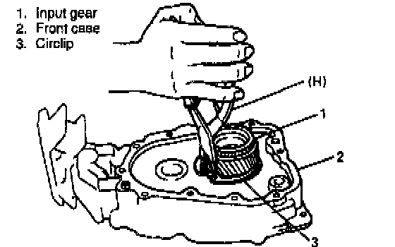
26. Using special tool, remove circlip of input gear bearing from front case.
NOTE: Be sure to use right tool to ensure proper work.
Special Tool
(H): 09900-06108
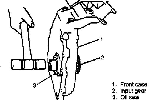
27. Using plastic hammer, drive gear out of case.
NOTE:
^ Be careful not to damage oil seal by hitting.
^ If removed, do not reuse oil seal.
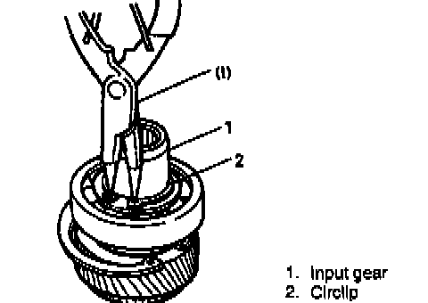
28. Remove circlip of input gear by using special tool.
Special Tool
(i): 09900-06107
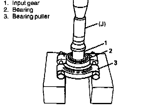
29. Remove bearing by using puller and press.
NOTE: Use metal pad for this removal, or gear spline may get damaged.
Special Tool
(J): 09951-76010
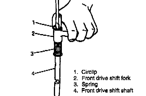
30. With spring on front drive fork shaft compressed, remove circlip and then remove fork and spring.
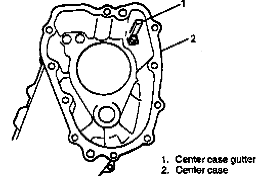
31. Remove oil gutter with wrench.