Electronic Shift Control System
ELECTRONIC SHIFT CONTROL SYSTEM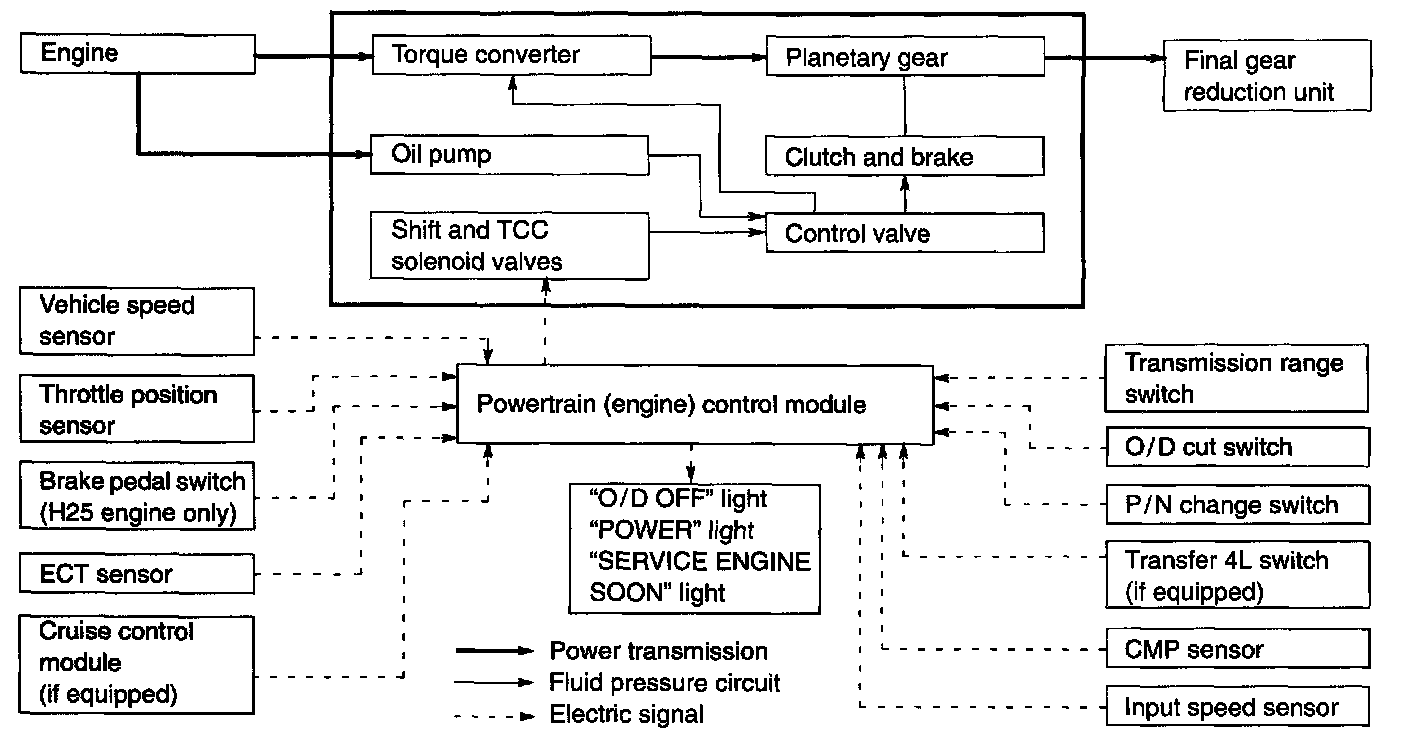
The gear ratio change in "D" or "2" range and torque converter clutch operation are controlled by Powertrain (Engine) Control Module.
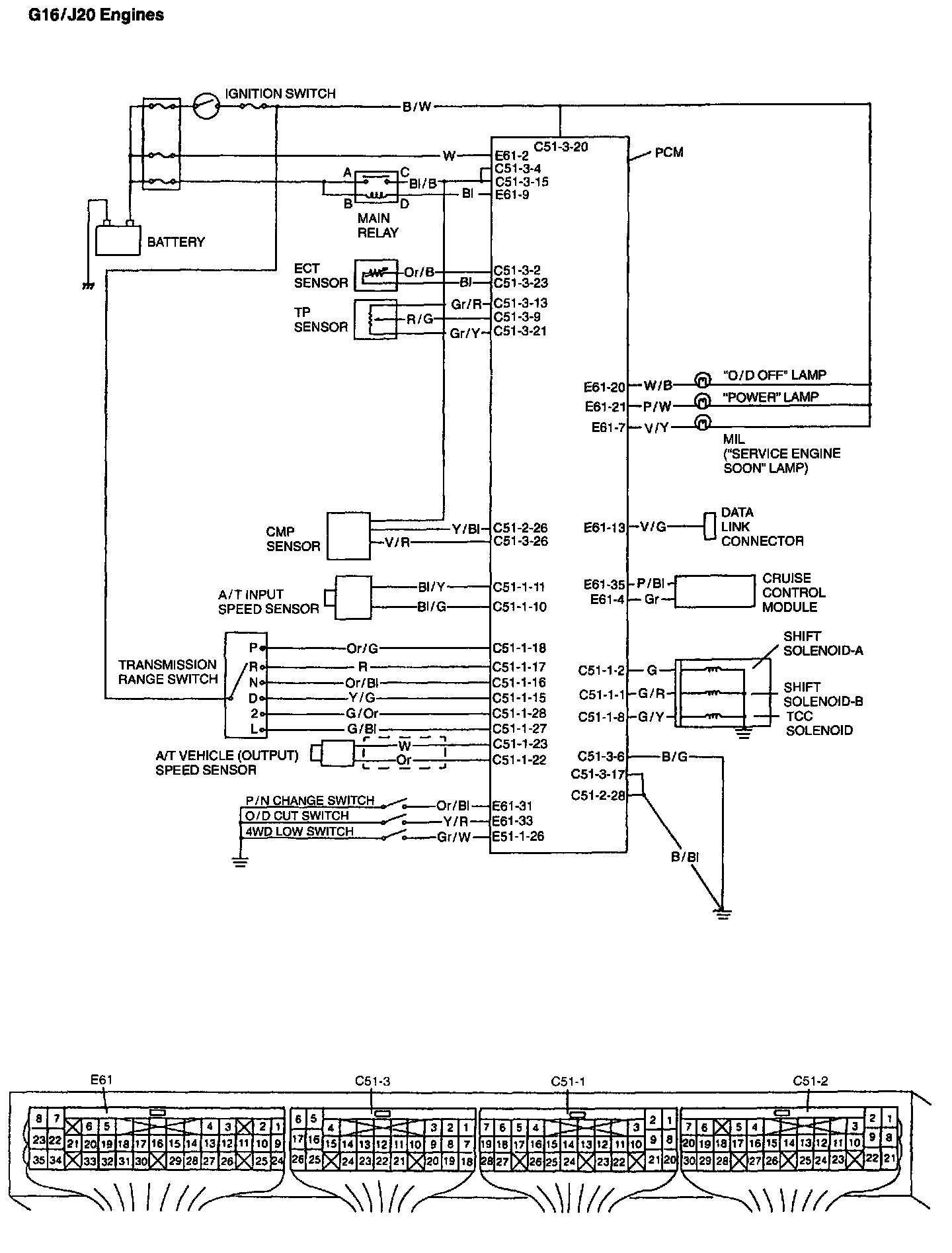
G16/J20 Engines - Schematic
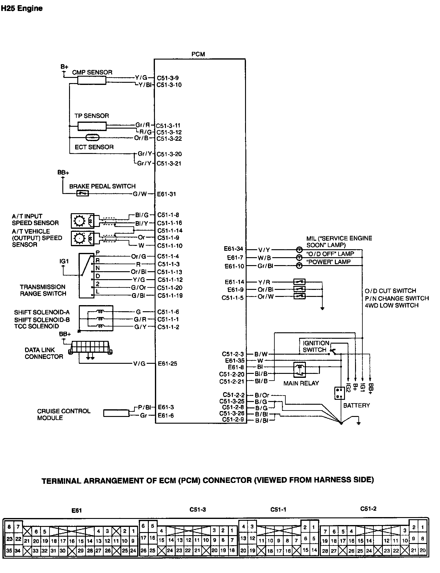
H25 Engines - Schematic
Fail Safe Function
This function is provided by the safe mechanism that assures safe driveability even when the shift solenoid valve or speed sensor fails.
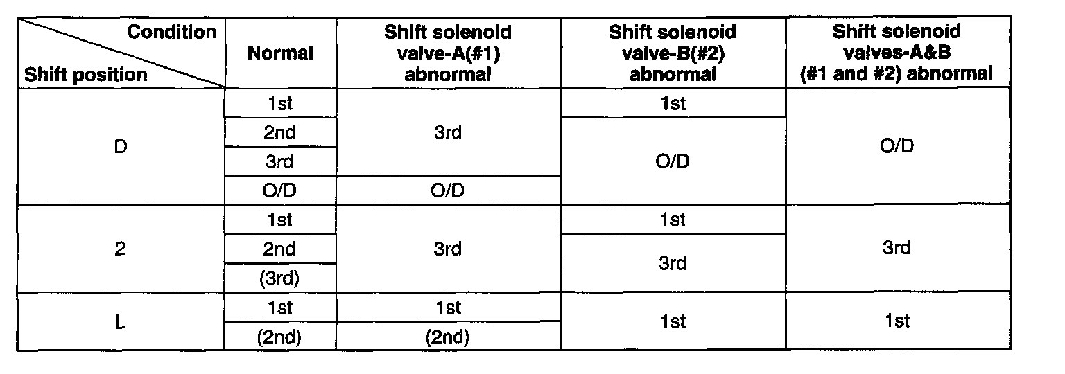
The table shows the gear position in each shift under a normal/abnormal condition.
Change Mechanism
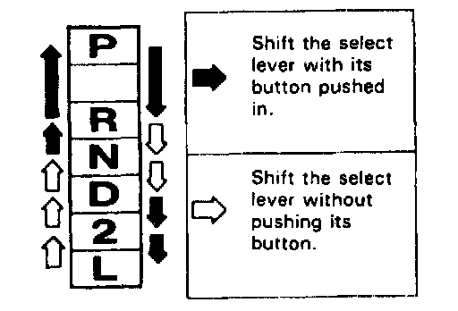
The same select pattern shift lever is used as the floor type and frequently used "N" and "D" ranges are made selectable freely.
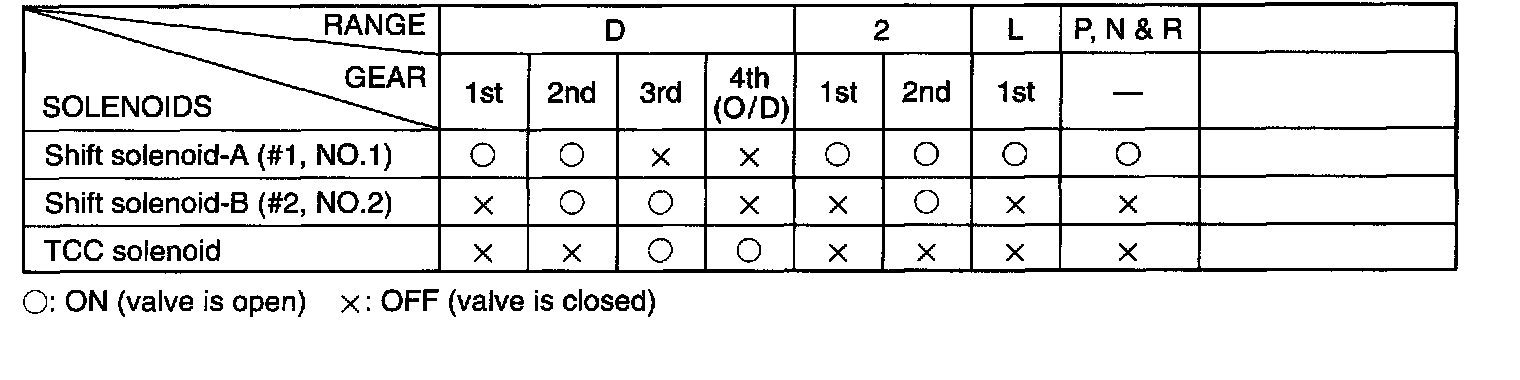
Operation of Shift Solenoids and TCC Solenoid
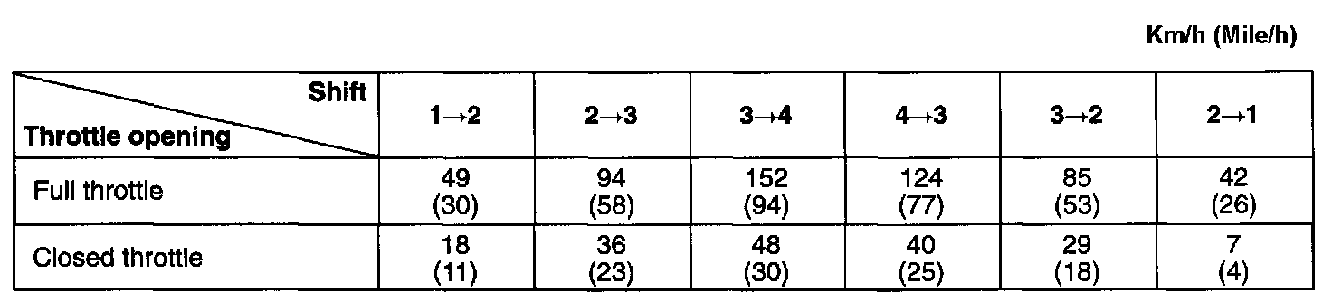
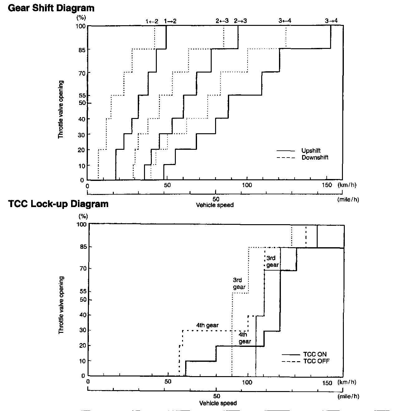
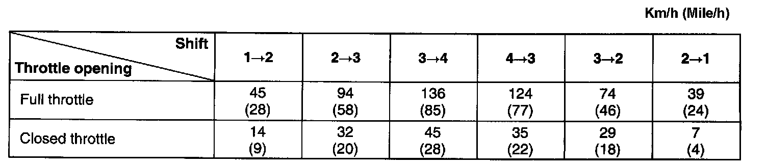
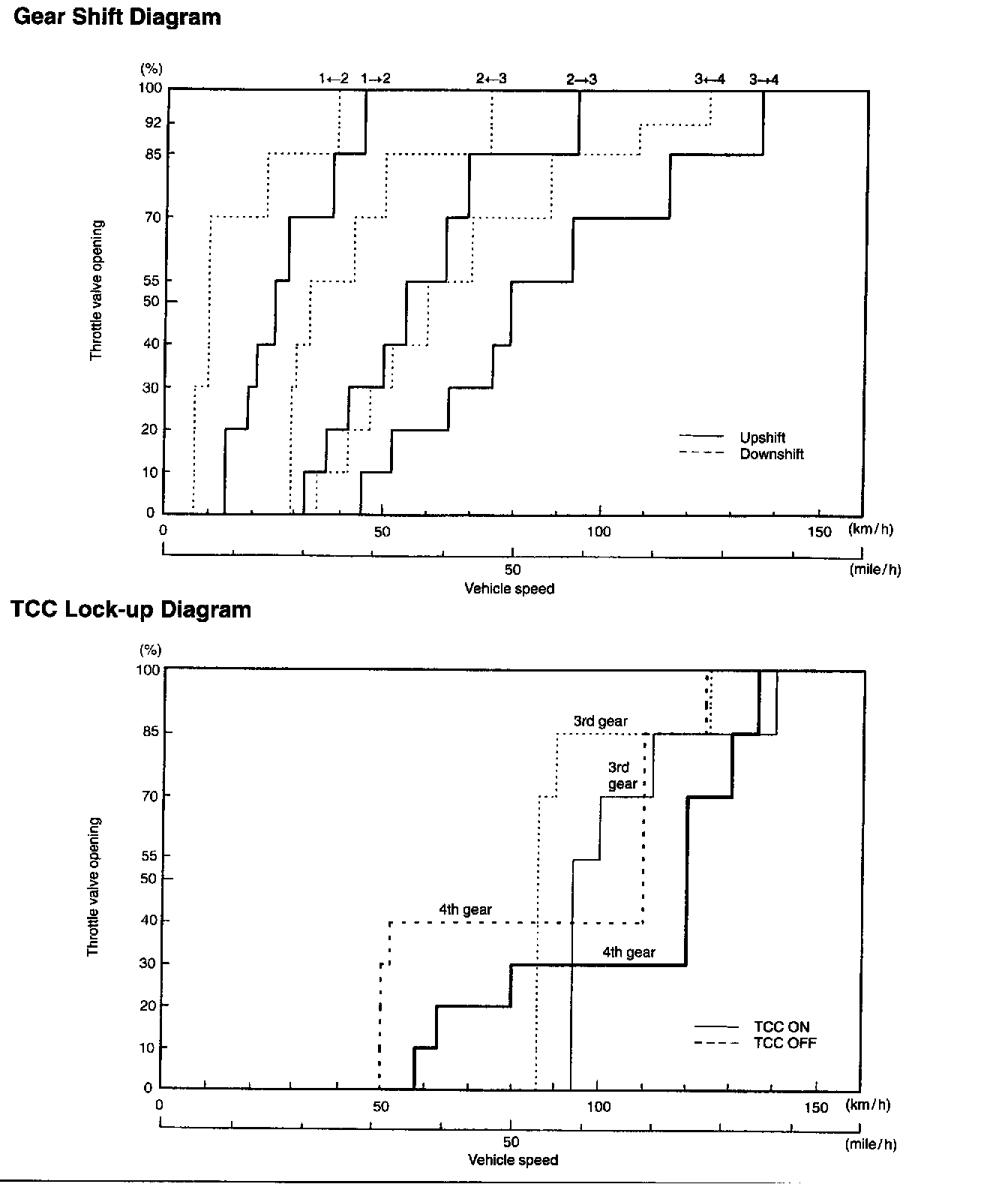
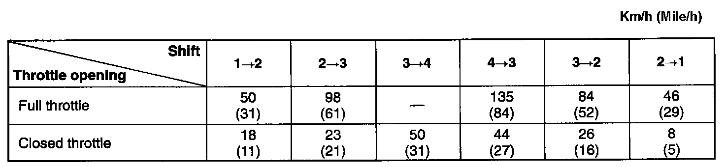
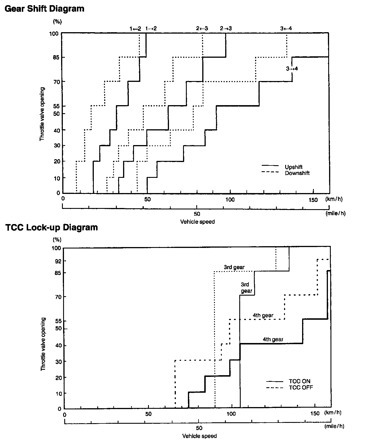
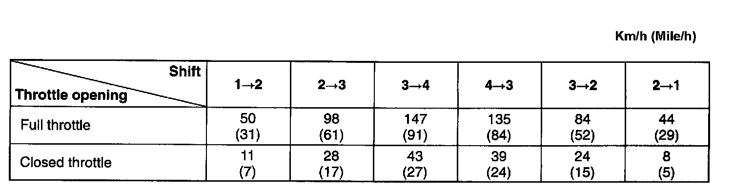
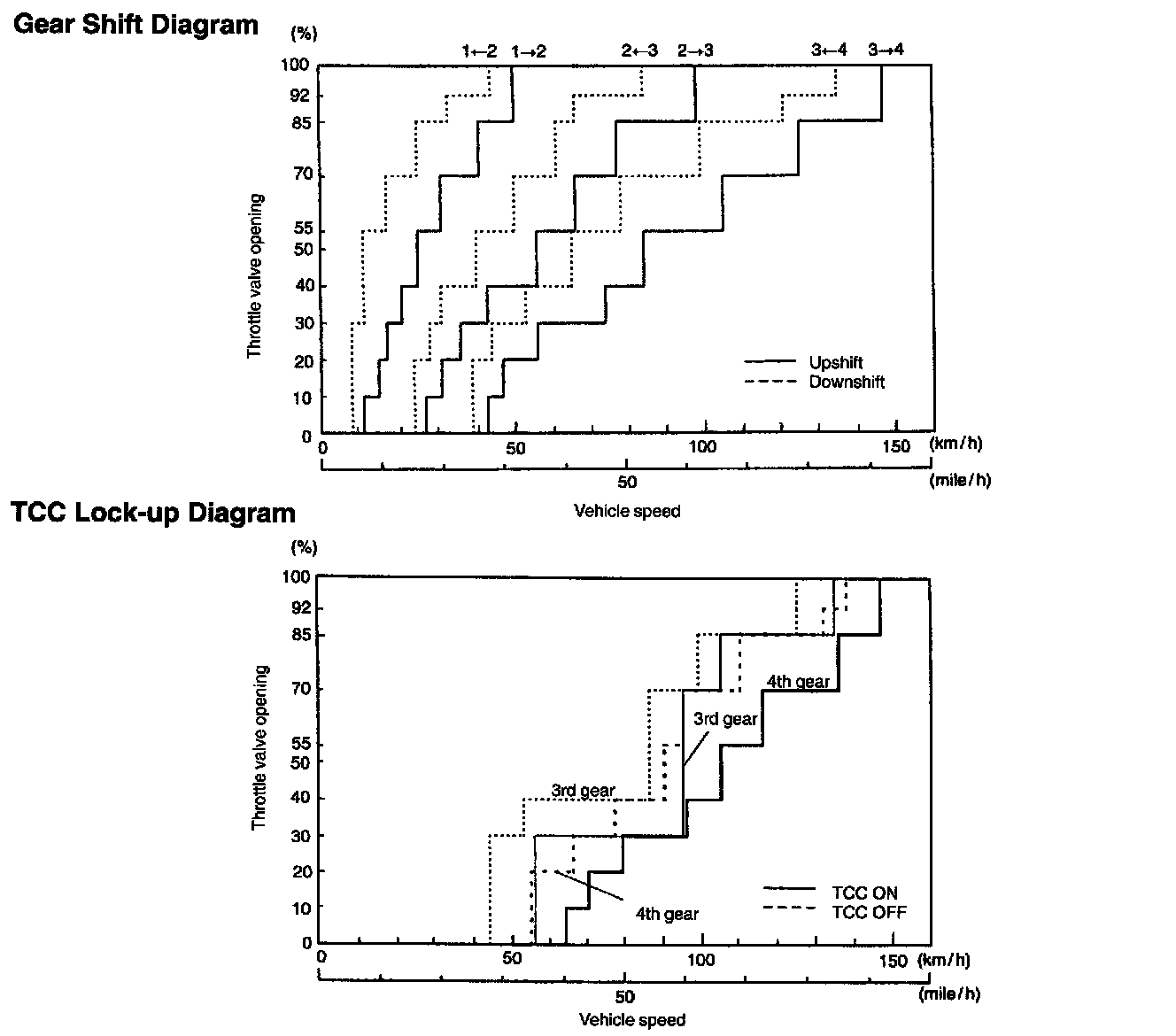
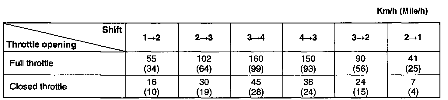
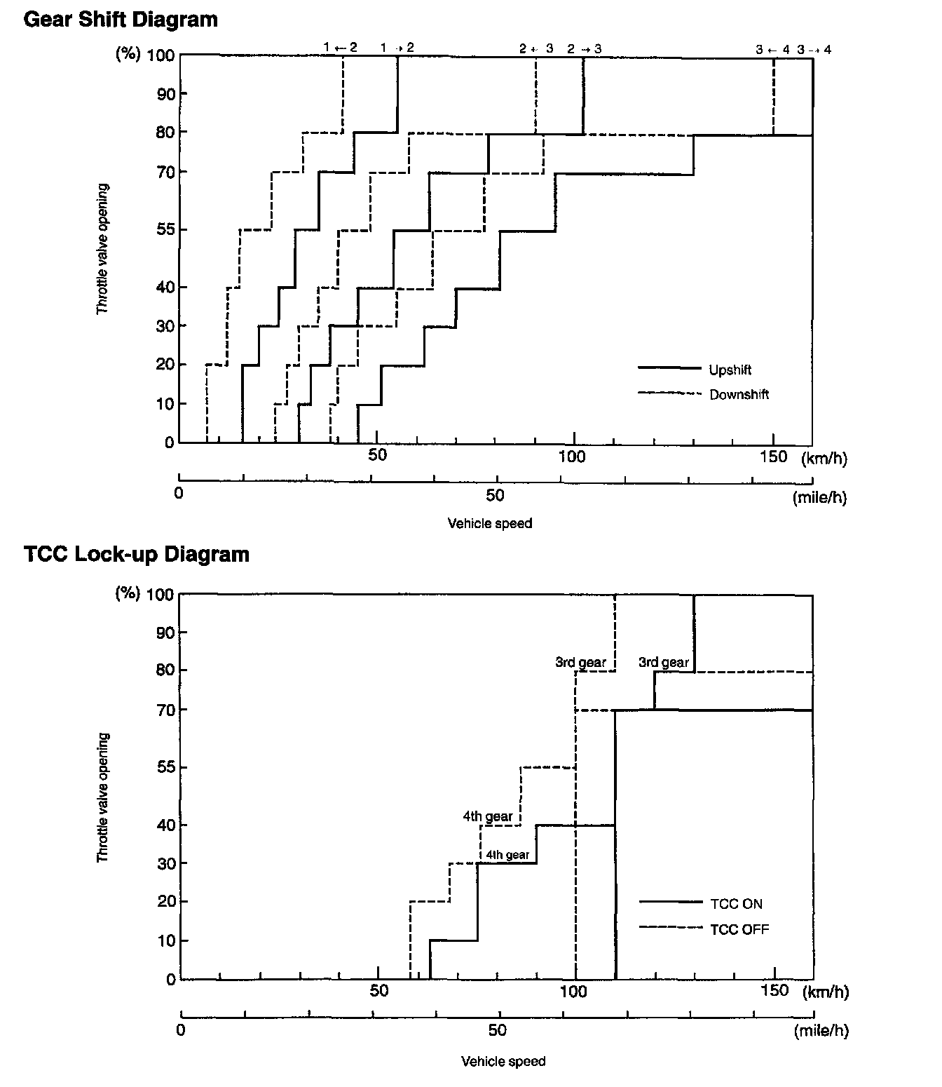
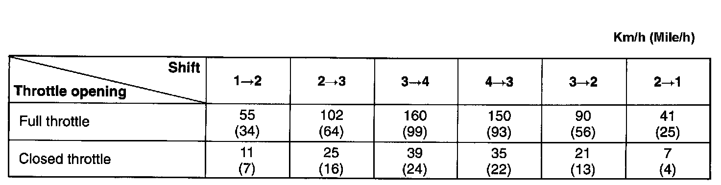
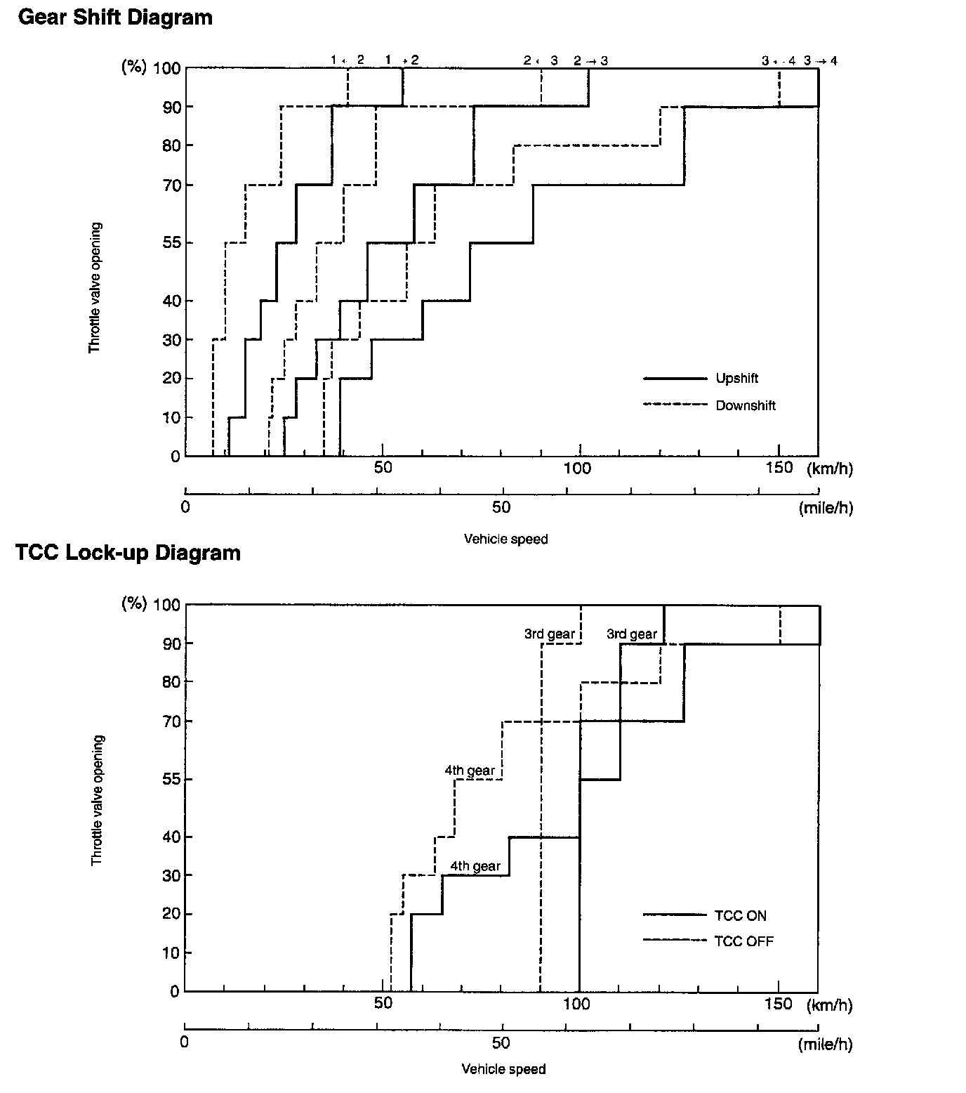
AUTOMATIC GEAR SHIFT DIAGRAM
Automatic shift schedule as a result of shift control is shown below. In case that select lever is shifted to L at a higher than 52 km/h or 33 mile/h speed for G16 engine (43 km/h or 27 mile/h for J20 engine, 55 km/h or 34 mile/h for H25 engine), 2nd or 3rd gear is operated and then down shifts to 1st at a speed lower than that. No up shift is available in L.
The same as, the select lever is shifted to 2 at a higher than 102 km/h (64 mile/h) speed for G1 6/J20 engines (105 km/h or 65 mile/h for H25 engine), 3rd gear is operated and then down shifts to 2nd at a speed lower than that.
Power Mode For G16 Engine
Normal Mode For G16 Engine
Power Mode For J20 Engine
Normal Mode For J20 Engine
Power Mode For H25 Engine
Normal Mode For H25 Engine