P0455
SYSTEM/CIRCUIT DESCRIPTIONWhile engine running, ECM closes EVAP canister air valve and opens EVP canister purge valve. It EVAP control system is in good condition, EVAP control system pressure that detected by fuel pressure sensor becomes down. After that, ECM closes EVAP canister purge valve leaving EVAP canister air valve is closed. If EVAP emission control system is in good condition, the fuel tank pressure rises specified rate.
Wiring Diagram:

Detecting Condition / Trouble Area:

DTC CONFIRMATION PROCEDURE
WARNING:
- When performing a road test, select a place where there is no traffic or possibility of a traffic accident and very careful during testing to avoid occurrence of an accident.
- Road test should be carried out with 2 person, a driver and tester, on a level road.
NOTE:
Check to make sure that the following conditions are satisfied when using this DTC CONFIRMATION PROCEDURE.
- Engine coolant temp. at engine start: Between -10 °C and 110 °C (14 °F and 230 °F)
- Intake air temp.: Between -10 °C and 60 °C (14 °F and 140 °F)
- Altitude (barometric pressure): 2400 m, 8000 ft or less (560 mm Hg, 75 kPa or more)
- Fuel level indication on meter cluster: 314 or less (For 1999 MY)
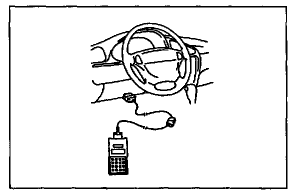
1. With ignition switch OFF, connect scan tool.
2. Turn ON ignition switch and clear DTC using scan tool.
3. Start engine and warm up to normal operating temperature.
4. Drive vehicle at 40 mph (60 kph ) or more for 12 min.
5. Keep vehicle speed at 40 mph (60 kph ) for 3 min. (Throttle valve opening is kept constant in this step.)
6. Stop vehicle and check if DTC and pending DTC exists using scan tool. If not, check if evaporative system monitoring test has completed using scan tool. If not in both of above checks (i.e., no DTC/pending DTC and evaporative system monitoring test not completed), check vehicle conditions (environmental) and repeat step 3. through 6..
Troubleshooting (Steps 1 - 11):

Troubleshooting (Steps 12 - 17):

EVAP Canister Purge Valve and Its Circuit Inspection
1. Prepare to operate EVAP canister purge valve as follows.

When using SUZUKI scan tool:
1. Connect SUZUKI scan tool to DLC with ignition switch OFF and disconnect purge valve vacuum hoses from pipes.
2. Turn ignition switch ON, clear DTC and select "MISC TEST" mode on SUZUKI scan tool.

When not using SUZUKI scan tool:
1. Disconnect purge valve vacuum hoses from pipes.
2. Turn ignition switch ON.
Using service wire, ground C20-6 terminal of ECM connector (valve ON) and unground it (valve OFF).

2. Check purge valve for operation and vacuum passage for clog when valve is switched ON and OFF by using SUZUKI scan tool or service wire.
Valve OFF: When blowing into hose "A", air should not come out of hose "B".
Valve ON: When blowing into hose "A", air should come out of hose "B".
If check result is not described, check vacuum hoses, purge valve, wire harness and connections.
EVAP Canister Purge Valve Inspection

1. With ignition switch OFF, disconnect coupler from canister purge valve.
2. Check resistance of EVAP canister purge valve.
Resistance between two terminals : 30 - 34 Ohms at 20 °C (68 °F)
Resistance between terminal and body :1 MOhms or higher
If resistance is as specified, proceed to next operation check. If not, replace.

3. Disconnect vacuum hoses.
4. With coupler disconnected, blow into hose "A". Air should not come out of hose "B".
5. Connect 12 V-battery to EVAP canister purge valve terminals. In this state, blow hose "A". Air should come out of hose "B".
WARNING: Do not suck the air through valve. Fuel vapor inside valve is harmful.
If check result is not described, replace purge valve.
EVAP Canister Air Valve and Its Circuit Inspection
1. Prepare to operate EVAP canister air valve as follows.

When using SUZUKI scan tool:
1. Connect SUZUKI scan tool to DLC with ignition switch OFF.
2. Turn ignition switch ON, clear DTC and select "MISC TEST" mode on SUZUKI scan tool.

When not using SUZUKI scan tool:
1. Turn ignition switch ON.
2. Using service wire, ground E91 -16 terminal of ECM connector (valve ON) and unground it (valve OFF).

2. Check EVAP canister air valve for operation and clog when valve is switched ON and OFF by using SUZUKI scan tool or service wire.
Valve OFF: When blowing into nozzle "A", air should come out of nozzle "B".
Valve ON: When blowing into nozzle "A", air should not come out of nozzle "B".
If check result is not described, check air valve wire harness and connections.
Tank Pressure Control Solenoid Valve and Its Circuit Inspection
1. Prepare to operate tank pressure control solenoid valve as follows.

When using SUZUKI scan tool:
1. Connect SUZUKI scan tool to DLC with ignition switch OFF.
2. Turn ignition switch ON, clear DTC and select "MISC TEST" mode on SUZUKI scan tool.

When not using SUZUKI scan tool:
1. Turn ignition switch ON.
2. Using service wire, ground E91 -26 terminal of ECM connector (valve ON) and unground it (valve OFF).

2. Check pressure control solenoid valve for operating sound when valve is switched ON and OFF by using SUZUKI scan tool or service wire.
If no sound is heard, check wire harness, connections and tank pressure control solenoid valve.
EVAP Leakage Inspection
1. Disconnect purge hose from purge valve.
2. Disconnect EVAP canister air suction hose from body and plug it.
3. Connect SUZUKI scan tool to DLC with ignition switch OFF.
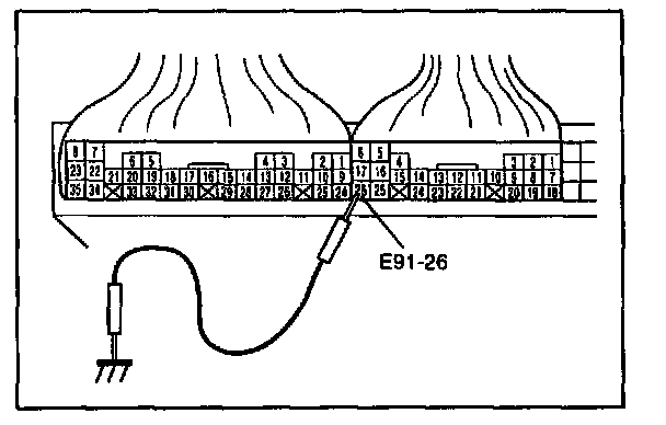
4. Turn tank pressure control solenoid valve ON (Valve open) by grounding E91-26 terminal of ECM connector connected to ECM.
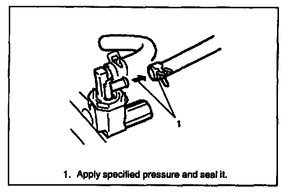
5. While observing tank pressure displayed on SUZUKI scan tool, apply 3.5 kPa, 14 in.Aq, 26 mmHg pressure into purge hose and fuel tank and seal it.
After 15 sec., check to make sure that pressure is higher than 3.3 kpa, 13.6 in.Aq, 24.5 mmHg.
If check result is not satisfactory, locate pressure leaking point by using soap water or leak detector.
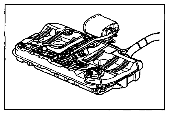
If no pressure leakage exists in vapor purge line, fuel filler cap, filler neck and etc., remove fuel tank from vehicle and check for leakage from installation face of parts installed on fuel tank, hose joint, tank pressure control valves, tank pressure control solenoid valve and refuel vapor control valve.