Components Description
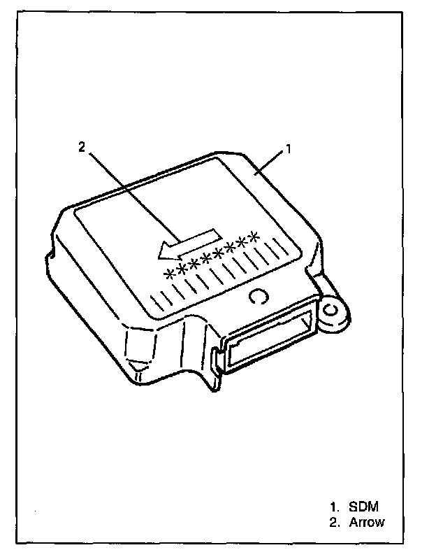
SDM (SENSING AND DIAGNOSTIC MODULE)
WARNING:
- During service procedures, be very careful when handling a Sensing and Diagnostic Module (SDM).
- Be sure to read SERVICE PRECAUTIONS and HANDLING PRECAUTIONS before starting to work and observe every precaution during work. Neglecting them may result in personal injury or undeployment of the air bag when necessary.
CAUTION: After detecting one time of such collision as to meet deployment condition, the SDM must not be used. Replace with new one. Refer to DIAGNOSIS when checking the SDM.
Sensing and Diagnostic Module (SDM) is designed to perform the following functions in air bag system:
1. Energy Reserve
SDM maintains Reserve energy supply to provide deployment energy after ignition voltage is lost in a frontal crash.
2. Frontal Crash Detection
SDM monitors vehicle velocity changes to detect frontal crashes which are severe enough to warrant deployment.
3. Air Bag Deployment
When a frontal crash of sufficient force is detected, SDM will cause enough current to flow through air bag (inflator) modules to deploy air bags.
4. Malfunction Detection
SDM performs diagnostic monitoring of air bag system electrical components and sets a diagnostic trouble code (DTC) when a malfunction is detected.
5. Malfunction Diagnosis
SDM displays air bag diagnostic trouble codes (DTCs) and system status information through the use of special tool (SUZUKI scan tool).
SDM with on-board diagnostic function provides air bag diagnostic trouble codes by flashing 'AIR BAG" warning lamp when on-board diagnosis function is used.
6. "AIR BAG" Warning Lamp Control
The light is turned "ON" to warn the driver of occurrence of a trouble and made to flash to check burned bulb of "AIR BAG" warning lamp.
7. Communication with SUZUKI scan tool
DTC display or DTC clear.
In response to the output request from SUZUKI scan tool, DTC recorded in the memory, each initiator circuit resistance and ignition voltage as recognized by SDM at time of the output request are provided.
DRIVER AIR BAG (INFLATOR) MODULE
WARNING:
- Never attempt to disassemble or repair driver air bag (inflator) module. If any abnormality is found, be sure to replace it with new one as an assembly.
- When handling it, be sure to read SERVICE PRECAUTION under PRECAUTIONS.
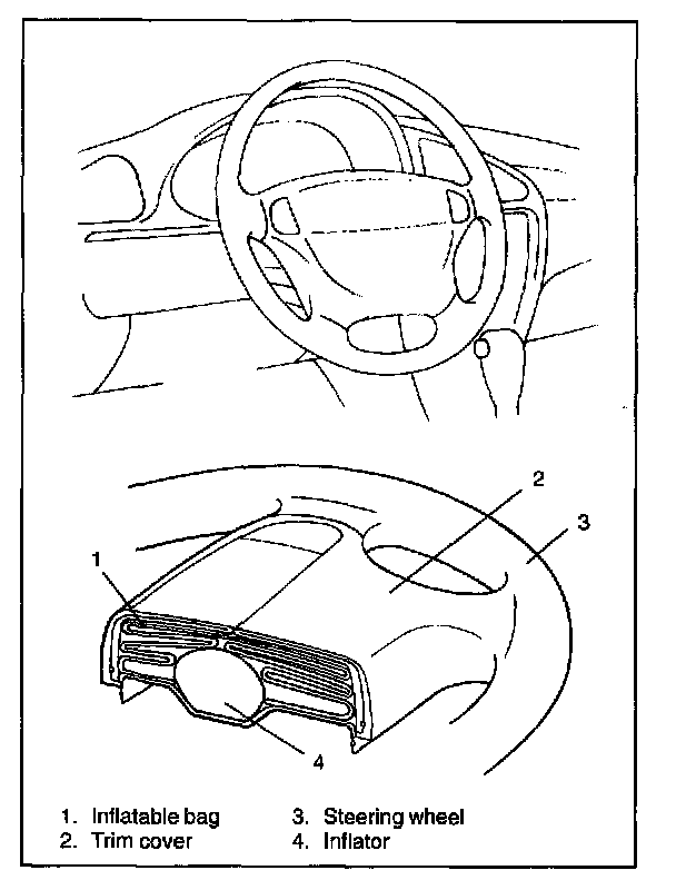
Driver air bag (inflator) module consists of inflatable bag, inflator and trim cover, and is mounted to the center of steering wheel.
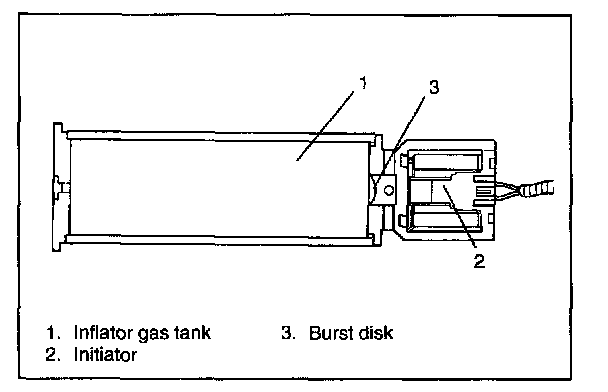
Driver inflator consists of initiator, burst disk and inflator gas tank. When vehicle is in a frontal crash of sufficient force, SDM causes current to flow through driver deployment loop. Current passing through the initiator causes a chemical reaction to occur. This chemical reaction generates pressure, depressing a burst disk which releases stored gas rapidly inflating air bag.
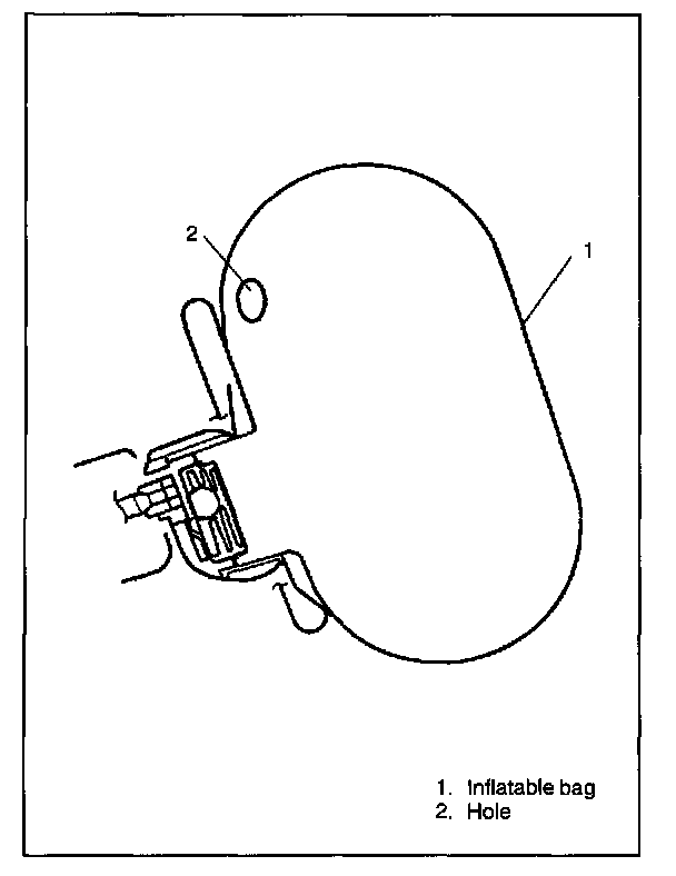
When inflatable bag deploys, its expansion force causes trim cover to open. Gas in the inflatable bag is let out through two exhaust holes in the back of bag at the right and left.
PASSENGER AIR BAG (INFLATOR) MODULE
WARNING:
- Never attempt to disassemble or repair passenger air bag (inflator) module. If any abnormality is found, be sure to replace it with new one as an assembly.
- When handling it, be sure to read SERVICE PRECAUTION and observe each instruction.
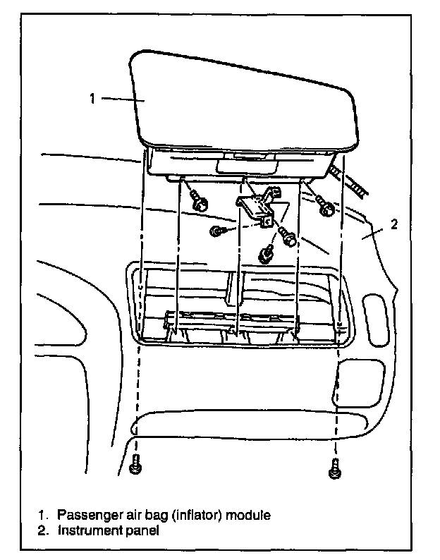
Passenger air bag (inflator) module consists of inflatable bag, inflator and trim cover, and is mounted above glove box in instrument panel on the passenger side.
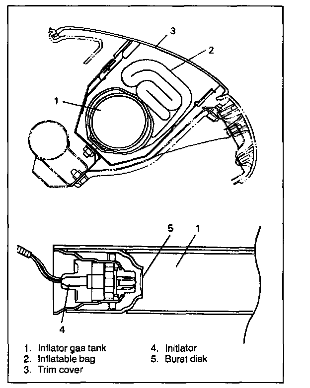
Passenger inflator consists of initiator, burst disk and inflator gas tank. When vehicle is in frontal crash of sufficient force, SDM causes current to flow through passenger deployment loop. Current passing through initiator causes a chemical reaction to occur. This chemical reaction generates pressure, depressing burst disk which releases stored gas rapidly inflating air bag.
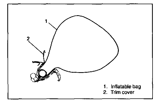
Once deployment starts, expansion force of the inflatable bag forces trim cover and move up.
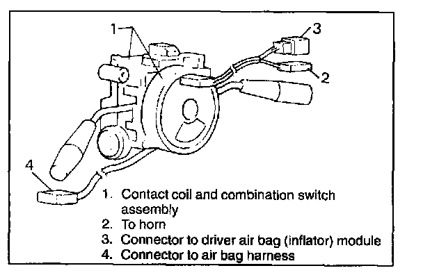
CONTACT COIL AND COMBINATION SWITCH ASSEMBLY
The contact coil assembly consists of three current carrying coils; two for the deployment loop and one for the horn circuit. The contact coil assembly is combined with the combination switch assembly and mounted together on the steering column, allowing rotation of the steering wheel while maintaining continuous contact of the driver deployment loop to the driver air bag (inflator) module.
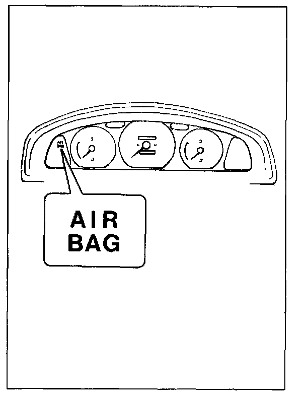
"AIR BAG" WARNING LAMP
The "AIR BAG" warning lamp is located in the combination meter and controlled by SDM.
The "AIR BAG" warning lamp is used in the air bag system to do the following:
- Verify lamp and SDM operation by flashing six times when the ignition switch is first turned "ON".
- When SDM detects a trouble, it causes "AIR BAG" indicator light to turn on to warn occurrence of a trouble to the driver. At the same time, it stores the trouble area in the back-up memory of SDM.
- When the diagnosis switch terminal is grounded, SDM indicates the trouble area by making "AIR BAG" indicator light flash.
The "AIR BAG" warning lamp is the key to driver notification of air bag system malfunctions. For proper lamp operation, refer to the AIR BAG DIAGNOSTIC SYSTEM CHECK in this section.
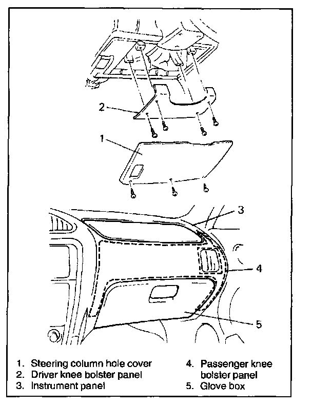
KNEE BOLSTERS
The knee bolsters are used to absorb energy and control the forward movement of the vehicle's front seat occupants during a frontal crash, by limiting leg movement.
STEERING COLUMN
The steering column is energy absorbing and is designed to compress in a frontal crash to decrease the chance of injury to the driver.
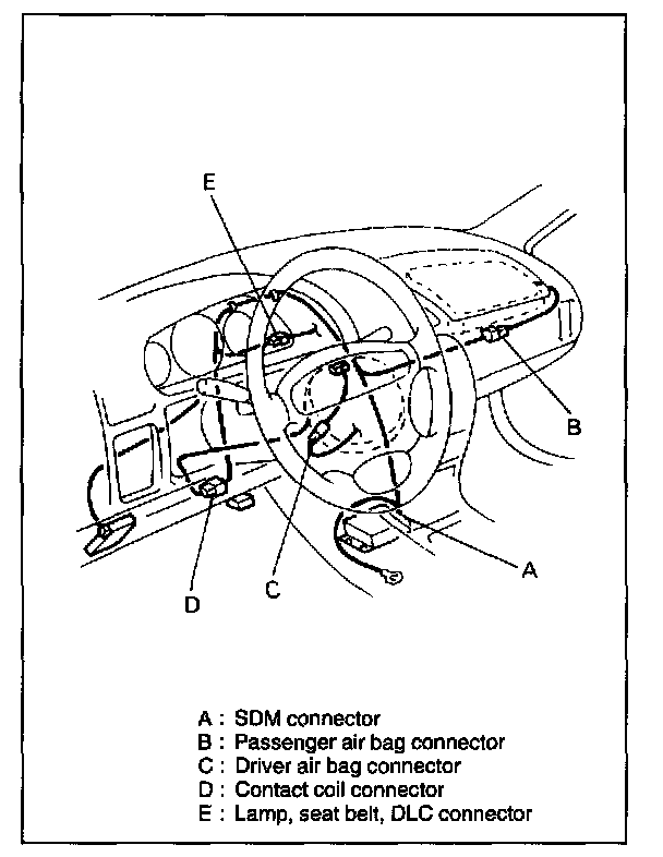
AIR BAG WIRE HARNESS AND CONNECTORS
CAUTION: When an open in wire harness, damaged wire harness, connector or terminals is found, replace wire harness, connectors and terminals as assembly
The air bag wire harness can be identified easily as it is covered with a yellow protection tube. Be very careful when handling it.
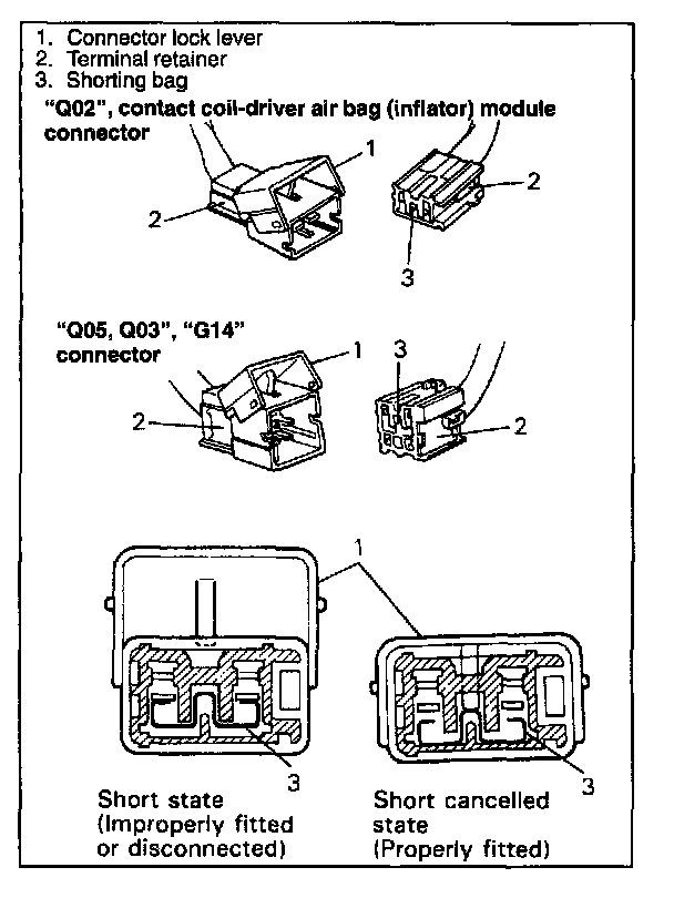
Each connector has a terminal lock mechanism (operated by the terminal retainer) and a connector lock mechanism (operated by connector lock lever). Also, connectors "A", "B", "C" and "D" have a short mechanism (operated by shorting bar).

A. SDM Connector
Connector lock lever:
The purpose of the connector lock lever is to assure the connector halves are securely connected and they cannot vibrate apart.
Shorting bar:
Connector "A" has a short mechanism which connects the "AIR BAG" lamp circuit to the ground while the connector is disconnected from SDM. When connected to SDM securely, it is automatically cancelled.
Terminal retainer (Terminal position assurance: TPA):
The function of the TPA is to keep the terminal securely seated in the connector body. The TPA is not to be removed from the connector body.
Terminal retainer (Terminal position assurance: TPA):
The function of the TPA is to keep the terminal securely seated in the connector body. The TPA is not to be removed from the connector body.
B. Passenger Air Bag (Inflator) Module Connector
C. Driver Air Bag (Inflator) Module Connector
D. Contact Coil Connector
E. Lamp, Seat Belt, DLC Connector
Connector lock lever:
Functions of the connector lock lever are: to connect connectors securely, to cancel shorts and to lock connectors against disconnection.
Shorting bar:
Function of the shorting bar is to short circuit the "HI" and "LO" terminals of the initiator circuit on its module side when the connector is disconnected. This prevents potential difference from occurring between both terminals to avoid malfunction.
Terminal retainer (Terminal position assurance: TPA):
The function of the TPA is to keep the terminal securely seated in the connector body. The TPA is not to be removed from the connector body.
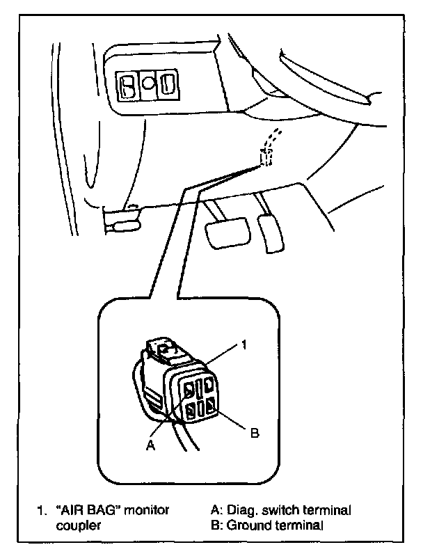
"AIR BAG" MONITOR COUPLER
"AIR BAG" monitor coupler has a diagnosis switch terminal and a ground terminal. With these terminals being shorted, "AIR BAG" warning lamp flashes to indicate the diagnostic trouble code.
(For details of diagnostic trouble code, DIAGNOSTIC TROUBLE CODE TABLE.)