Hydraulic Type
CLUTCH COVER CLUTCH DISC AND FLYWHEEL
Components
DISMOUNTING AND REMOUNTING OF TRANSMISSION
Refer to Manual Transmission/Transaxle.
REMOVAL
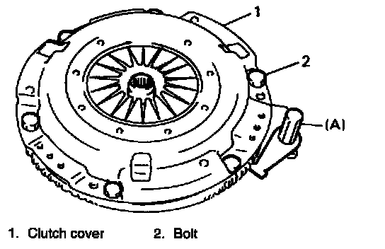
1. Hold flywheel stationary with special tool and remove clutch cover bolts, clutch cover and clutch disc.
Special Tool
(A): 09924-17810
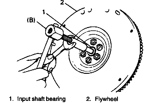
2. Pull out input shaft bearing by using special tool and wrench.
Special Tool
(B): 09917-58010

- When pulling out input shaft bearing from flywheel, use following special tools.
Special Tools
(B): 09921-20210
(C): 09930-30102
INSPECTION
Input Shaft Bearing
Check bearing for smooth rotation and replace it if abnormality is found.

Clutch Disc
Measure depth of rivet head depression, i.e. distance between rivet head and facing surface.
If depression is found to have reached service limit at any of holes, replace disc assembly.
Rivet head depth
"a": Standard 1.3 - 1.9 mm (0.051 - 0.074 inch)
Limit 0.5 mm (0.02 inch)
Clutch Cover
1. Check diaphragm spring for abnormal wear or damage.
2. Inspect pressure plate for wear or heat spots.
3. If abnormality is found, replace it as assembly.
Do not disassemble it into diaphragm and pressure plate.
Flywheel
Check surface contacting clutch disc for abnormal wear or heat spots. Replace or repair as required.
INSTALLATION
NOTE: Before assembling, make sure that flywheel surface and pressure plate surface have been cleaned and dried thoroughly.

1. Install flywheel to crankshaft and tighten bolts to specification.
Special Tool
(A): 09924-17810
Tightening Torque
(a): 70 Nm (7.0 kg.m, 51.0 ft. lbs.)

2. Using special tool, install input shaft bearing to flywheel.
Special Tool
(B): 09913-76010

3. Aligning clutch disc with flywheel center by using special tool, install clutch cover and bolts.
Then tighten bolts to specification.
NOTE:
- While tightening clutch cover bolts, compress clutch disc with special tool (clutch center guide) by hand so that disc is centered.
- Tighten cover bolts little by little evenly in diagonal order.
Special Tools
(A): 09924-17810
(C): 09923-36320
Tightening Torque
(b): 23 Nm (2.3 kg.m, 17.0 ft. lbs.)

4. Slightly apply grease to input shaft, then join transmission assembly with engine. Refer to Manual Transmission/Transaxle Service and Repair Removal and Installation for remounting procedure.
Removal and Installation
"A": SUZUKI SUPER GREASE. 1, 99000-25210
NOTE: When inserting transmission input shaft to clutch disc, turn crankshaft little by little to match the spline mesh.
CLUTCH RELEASE SYSTEM
Removal
1. Remove release arm by loosening its bolt.
2. Take out release bearing by turning release shaft.

3. Drive out No.2 bush by using special tool and hammer. Release shaft seal will also be pushed out.
Special Tool
(A): 09922-46010
4. Remove release shaft.

5. Pull No.1 bush out by using special tools.
Special Tools
(B): 09925-46010
(C): 09930-30102
Inspection
1. Check clutch release bearing for smooth rotation.
2. Inspect smoothness of release bearing retaining portion of transmission case and correct or replace right case as necessary.
CAUTION: Do not wash release bearing. Washing may cause grease leakage and consequential bearing damage.
Installation

1. Drive in a new No. 1 bush by using adequate drive handle and hammer and then apply grease to bush inside.
Special Tools
(A): 09943-88211
(B): 09923-46020 or the like
"A": SUZUKI SUPER GREASE A, 99000-25010
2. Install release shaft with return spring applied to it.

3. Apply grease to No.2 bush inside and press-fit it by using the same special tool as in removal.
"A": SUZUKI SUPER GREASE A
Special Tool
(C): 09922-46010
4. Coat grease to shaft seal and then install it till it is flush with case surface. Use special tool for this installation and face seal lip downward (inside).
"A": SUZUKI SUPER GREASE A
Special Tool
(D): 09925-98221
5. Caulk seal at A by using caulking tool and hammer.
6. Hook return spring.

7. Apply grease to release bearing inside and release shaft arm, then set bearing.
"A": SUZUKISUPER GREASE A, 99000-25010
8. Apply small amount of grease to input shaft spline and front end as well.
"B":SUZUKI SUPER GREASE 1, 99000-25210

9. Set release arm to release shaft aligning their punch marks, then tighten bolt.
Tightening Torque
(a): 13 Nm (1.3 kg.m, 9.5 ft. lbs.)