Inspection of P/S Control Module and Its Circuits
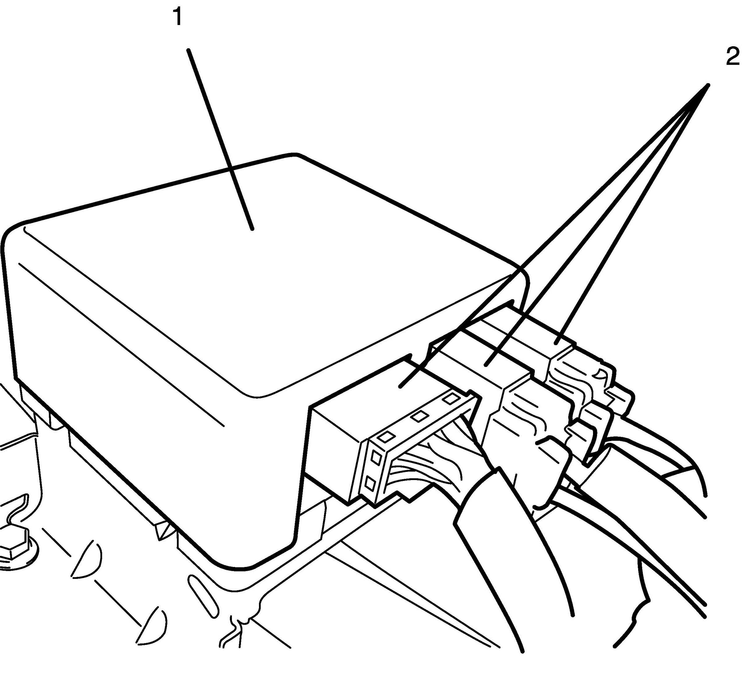
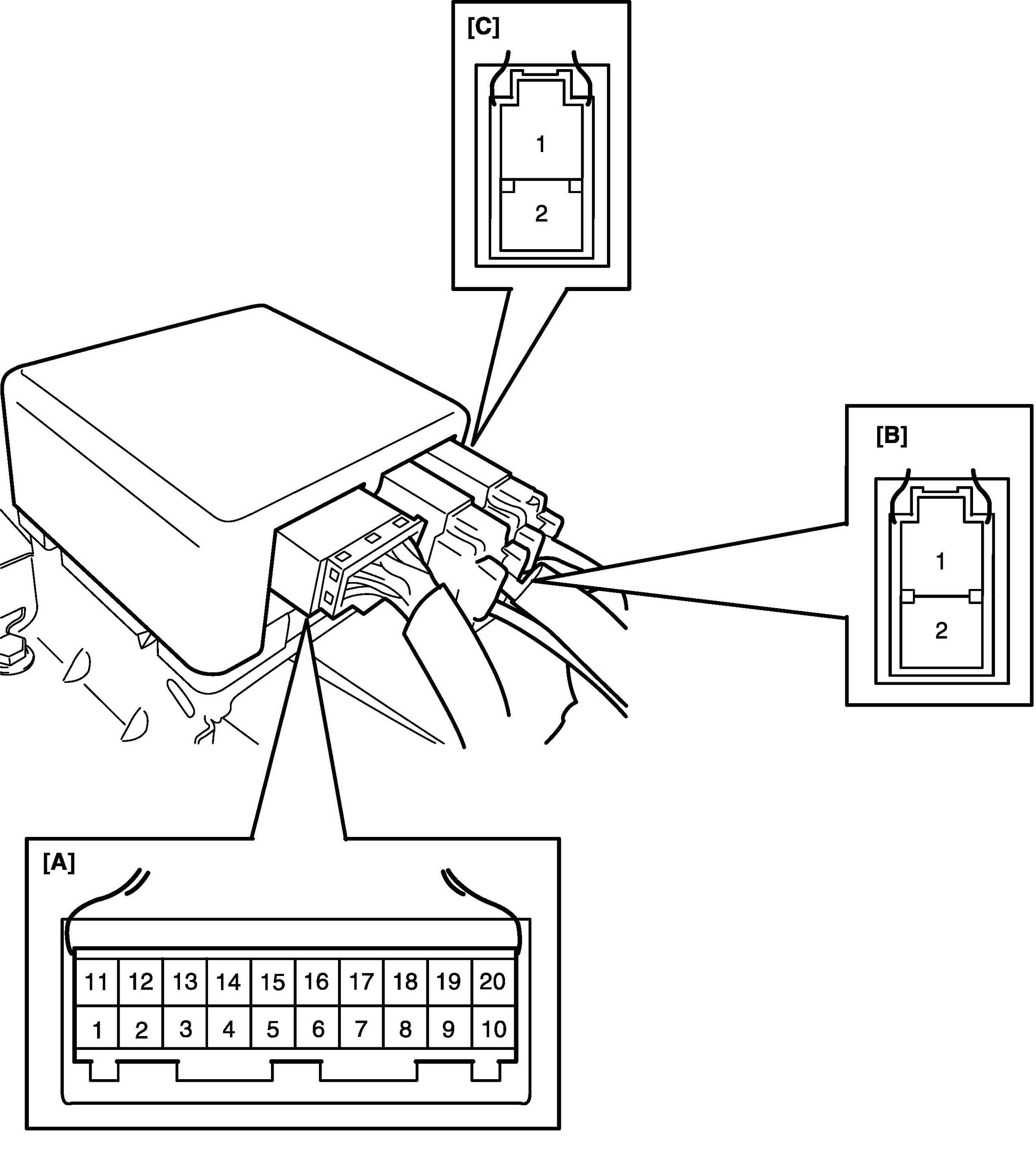
Inspection of P/S Control Module and Its CircuitsThe P/S control module (1) and its circuits can be checked at the P/S control module wiring couplers (2) by measuring voltage and resistance.
CAUTION: P/S control module cannot be checked by itself. It is strictly prohibited to connect voltmeter or ohmmeter to the P/S control module with connectors disconnected from the P/S control module.
Voltage Check
1. Remove console box.
2. Check for voltage at each terminal with connectors connected to the P/S control module.
NOTE: As each terminal voltage is affected by the battery voltage, confirm if the battery voltage is 11 V or more when ignition switch is ON.

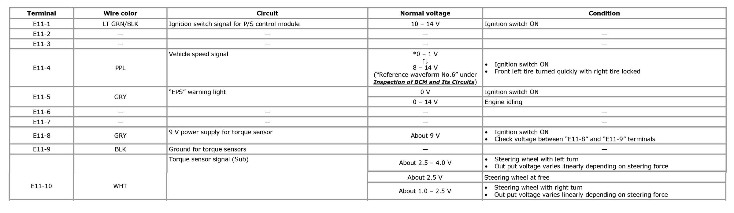
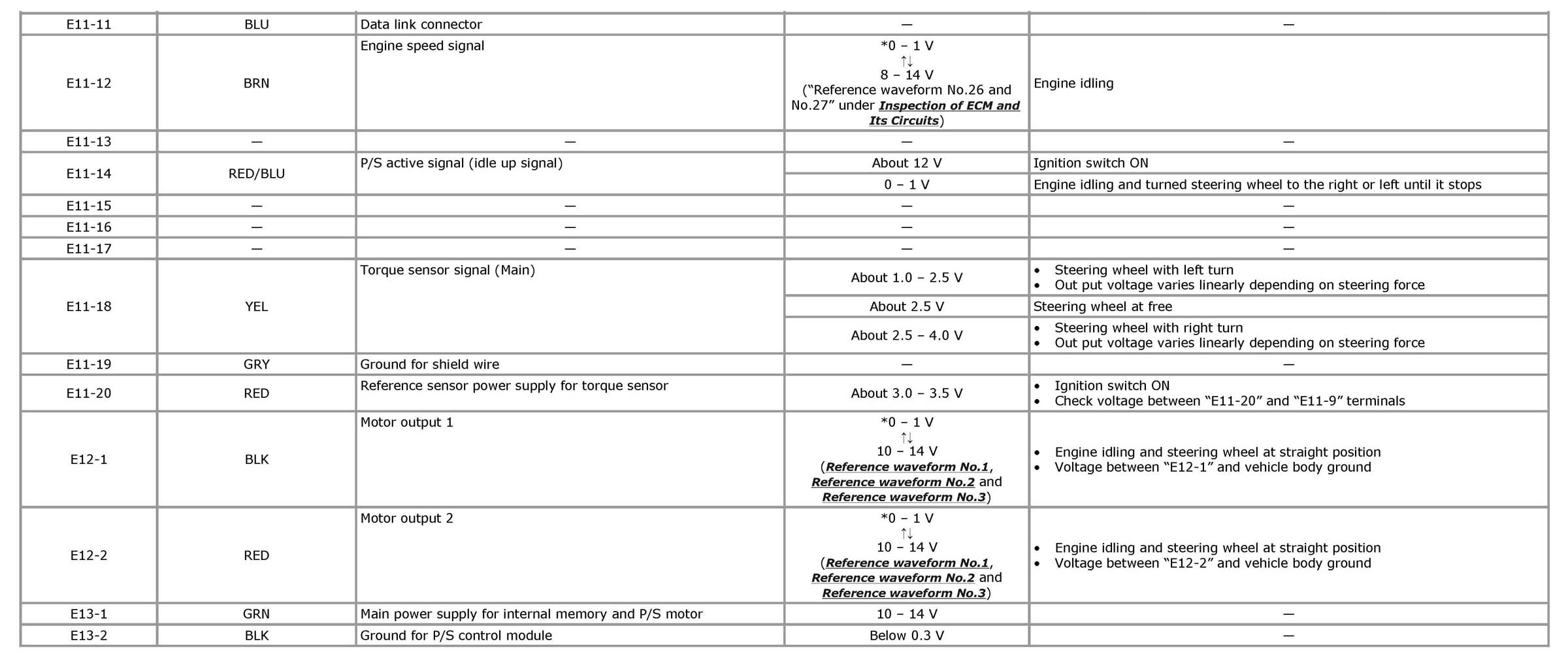
NOTE: *: The voltage of this circuit may not be checked by voltmeter. If so, use oscilloscope.
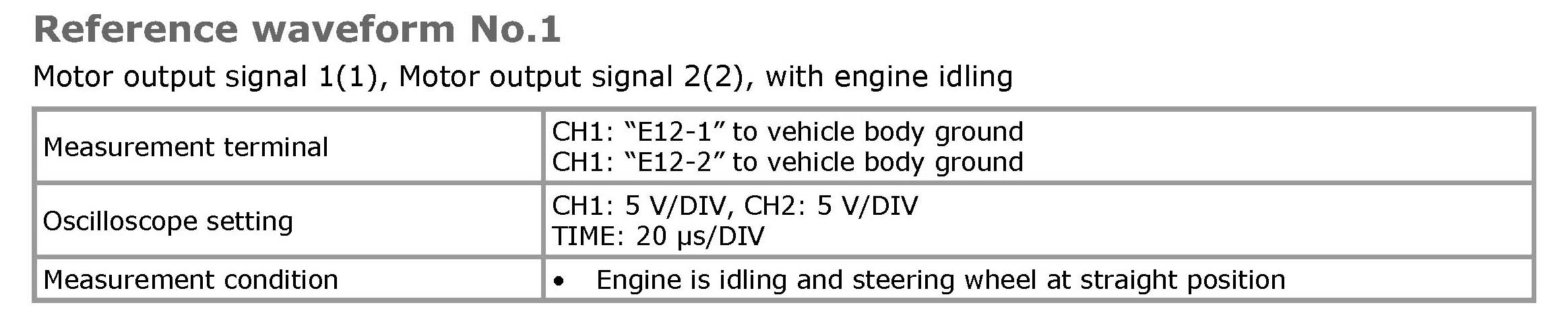
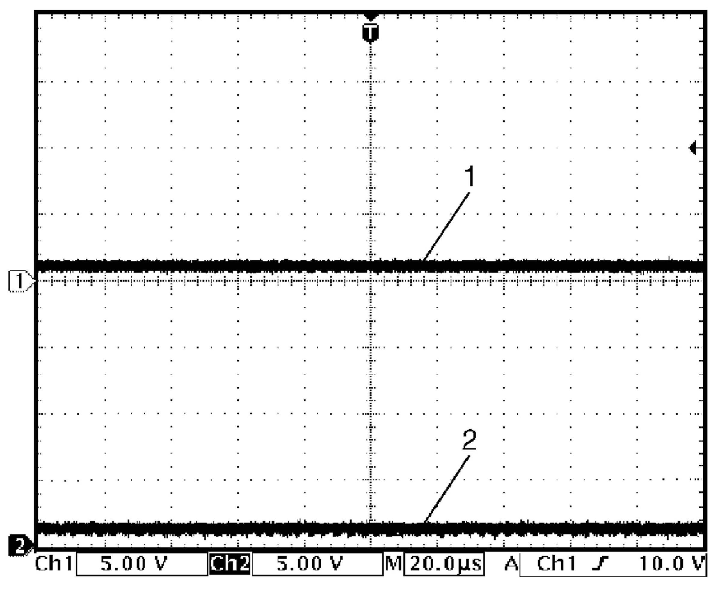
Reference waveform No.1
Motor output signal 1(1), Motor output signal 2(2), with engine idling
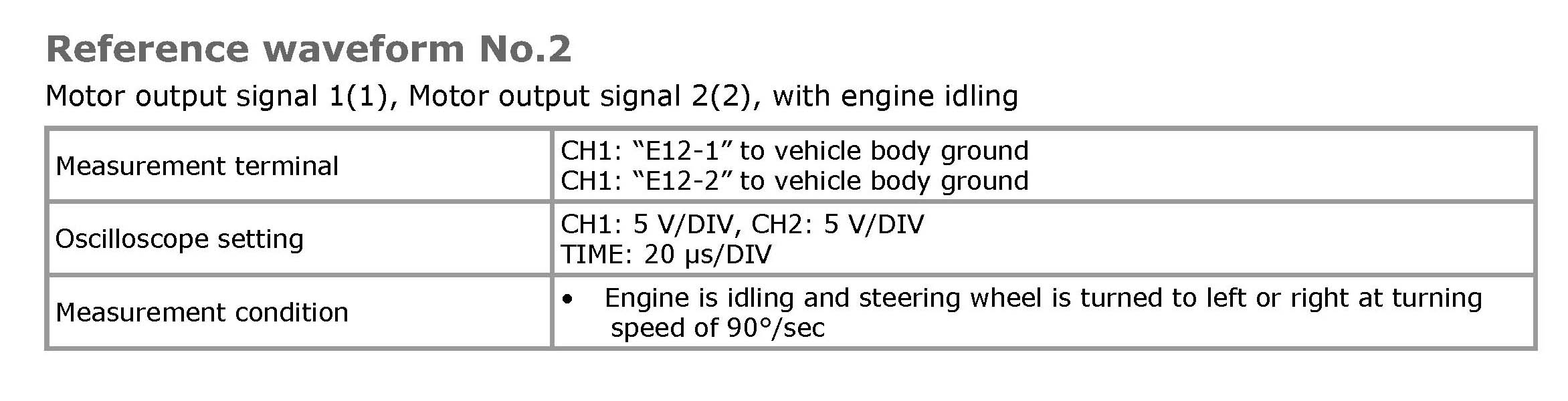
Reference waveform No.2
Motor output signal 1(1), Motor output signal 2(2), with engine idling
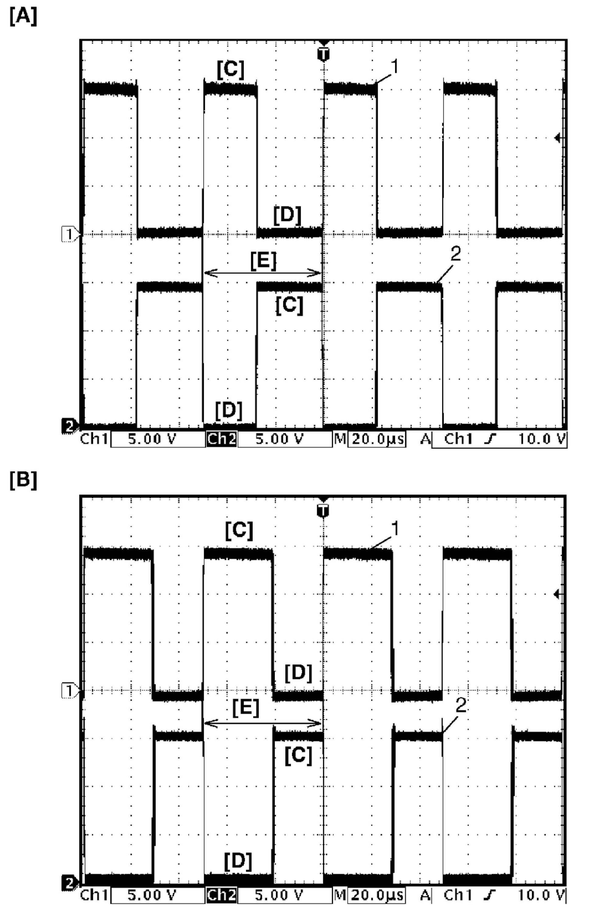
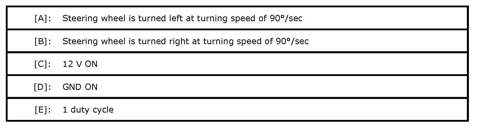
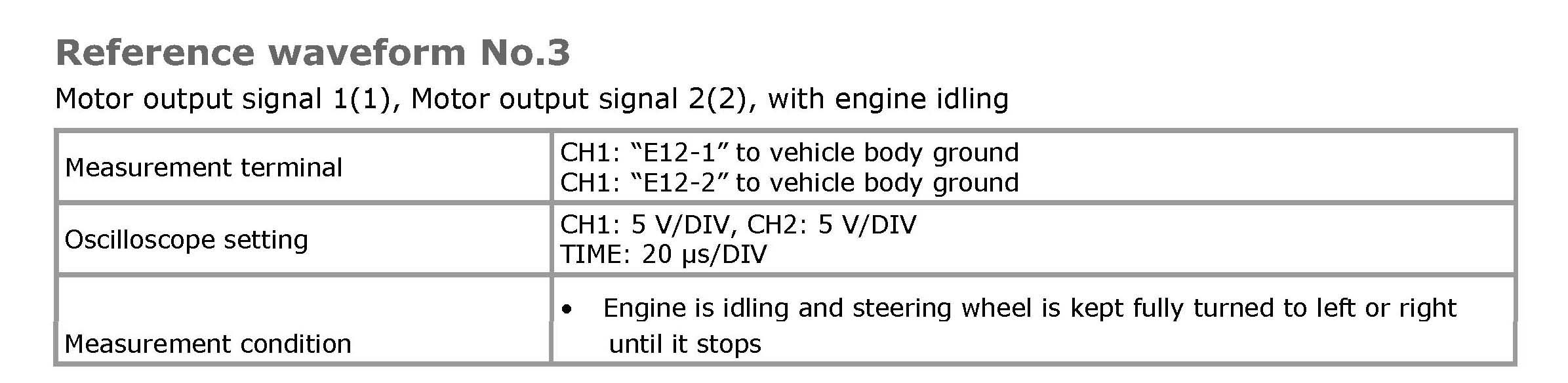
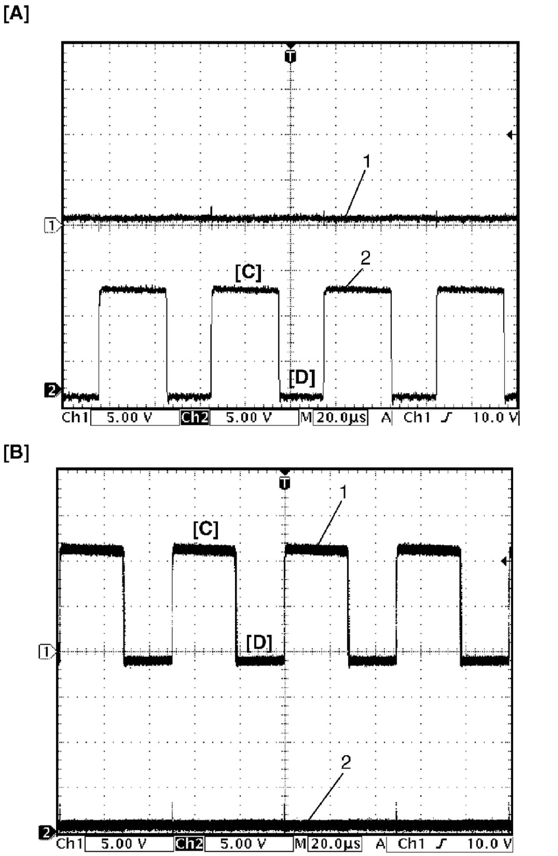
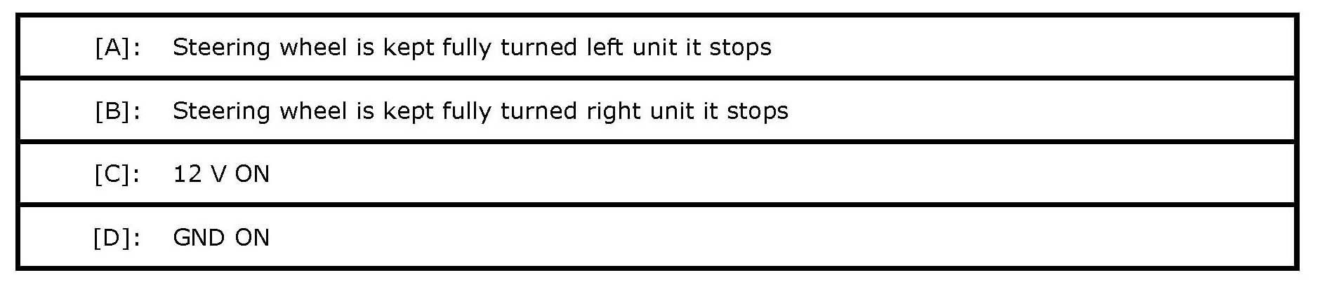
Reference waveform No.3
Motor output signal 1(1), Motor output signal 2(2), with engine idling