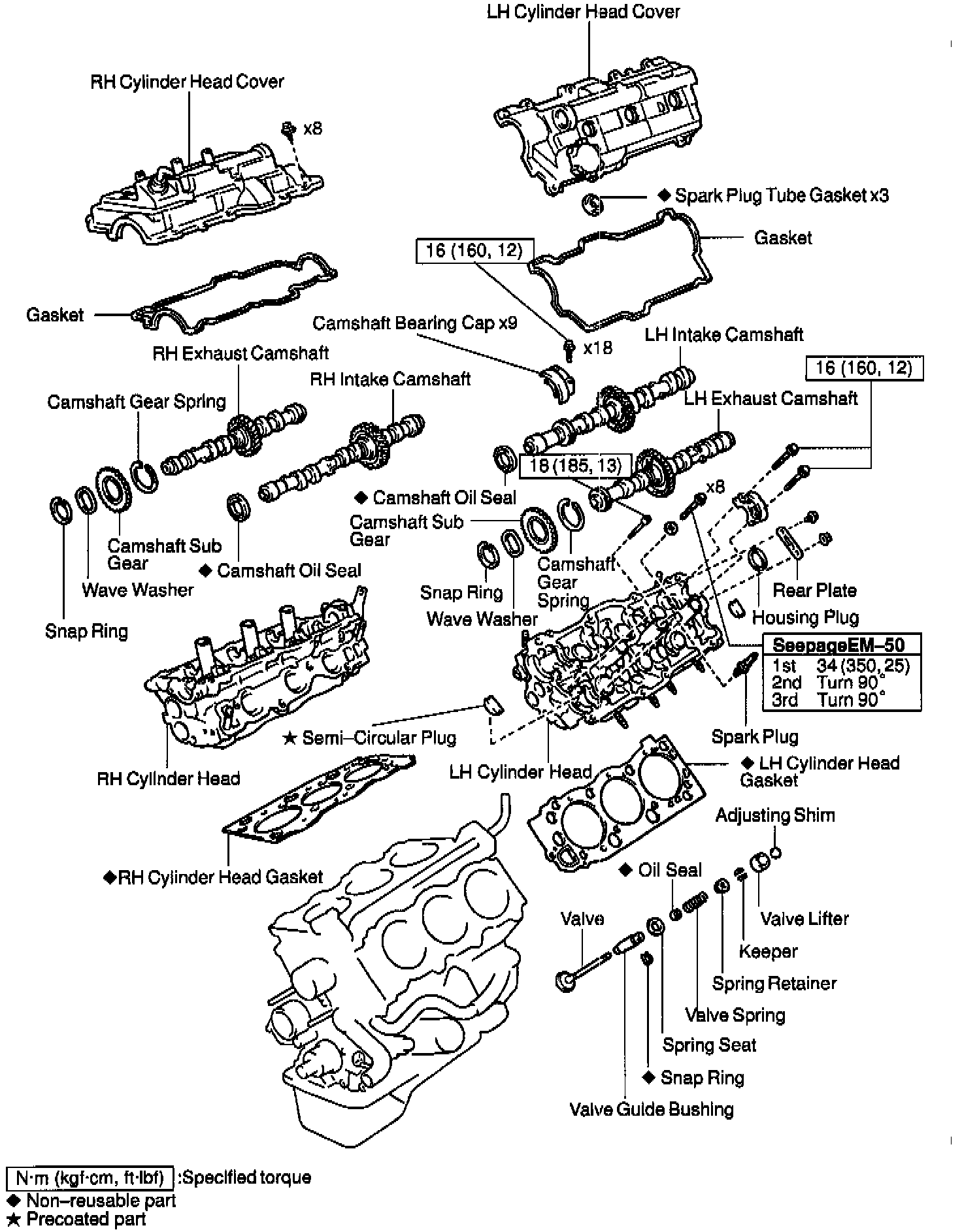
Cylinder Head Installation
INSTALLATION

1. PLACE CYLINDER HEAD ON CYLINDER BLOCK
a. Place 2 new cylinder head gaskets in position on the cylinder block.
NOTICE: Be careful of the installation direction.
b. Place the 2 cylinder heads in position on the cylinder head gaskets.
2. INSTALL 12 POINTED HEAD CYLINDER HEAD BOLTS

HINT:
^ The cylinder head bolts are tightened in 3 progressive steps (steps b, d and e).
^ If any bolt is broken or deformed, replace it.
a. Apply a light coat of engine oil on the threads and under the heads of the cylinder head bolts.
b. Install and uniformly tighten the cylinder head bolts on each cylinder head, in several passes, in the sequence shown, then repeal for the other side, as shown.
Torque: 34 Nm (25 ft. lbs.)
If any of the cylinder head bolts does not meet the torque specification, replace the cylinder head bolt.

c. Mark the front of the cylinder head bolt head with paint.
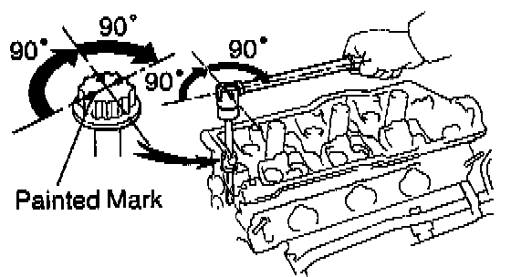
d. Retighten the cylinder head bolts by 90° in the numerical order shown.
e. Retighten the cylinder head bolts by an additional 90°.
f. Check that the painted mark is now facing rearward.

3. INSTALL RECESSED HEAD CYLINDER HEAD BOLTS
a. Apply a light coat of engine oil on the threads and under the heads of the cylinder head bolts.
b. Using an 8 mm hexagon wrench, install the cylinder head bolt on each cylinder head, then repeat for the other side, as shown.
Torque: 18 Nm (13 ft. lbs.)
4. CONNECT GROUND STRAP
Install the bolt and connect the ground strap.
5. ASSEMBLE EXHAUST CAMSHAFTS
a. Mount the hexagonal wrench head portion of the camshaft in a vise.
NOTICE: Be careful not to damage the camshaft.

b. Install these parts:
1) Camshaft gear spring
2) Camshaft sub-gear
HINT: Attach the pins on the gears to the gear spring ends.
3) Wave washer
c. Using snap ring pliers, install the snap ring.

d. Using Special Service Tool (SST), align the holes of the camshaft main gear and sub-gear by turning camshaft sub-gear clockwise, and temporarily install a service bolt.
SST 09960 - 10010 (09962 - 01000, 09963 - 00600)
e. Align the gear teeth of the main gear and sub-gear, and tighten the service bolt.
6. INSTALL CAMSHAFTS OF RH CYLINDER HEAD
NOTICE: Since the thrust clearance of the camshaft is small, the camshaft must be kept level while it is being installed. If the camshaft is not kept level, the portion of the cylinder head receiving the shaft thrust may crack or be damaged, causing the camshaft to seize or break. To avoid this, these steps should be carried out.

a. Install the intake camshaft.
1) Apply new engine oil to the thrust portion and journal of the camshaft.
2) Place the intake camshaft at 90° angle of timing mark (2 dot marks) on the cylinder head.

3) Apply MP grease to a new oil seal lip.
4) Install the oil seal to the camshaft.

5) Remove any old packing Formed In Place Gasket (FIPG) material.
6) Apply seal packing to the No.1 bearing cap as shown.
Seal packing: Part No. 08826 - 00080 or equivalent

7) Install the 5 tearing caps in their proper locations.

8) Apply a light coat of engine oil on the threads and under the heads of the bearing cap bolts.
9) Install and uniformly tighten the 10 bearing cap bolts, in several passes, in the sequence shown.
Torque: 16 Nm (12 ft. lbs.)

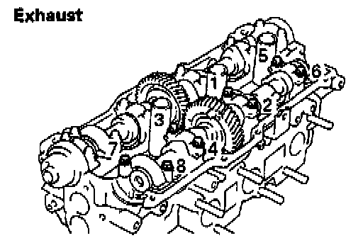
b. Install the exhaust camshaft.
1) Apply new engine oil to the thrust portion and journal of the camshaft.
2) Align the timing marks (2 dot marks) of the camshaft drive and driven gears.
3) Place the exhaust camshaft on the cylinder head.

4) Install the 4 bearing caps in their proper locations.

5) Apply a light coat of engine oil on the threads and under the heads of the bearing cap bolts.
6) Install and uniformly tighten the 8 bearing cap bolts, in several passes, in the sequence shown.
Torque: 16 Nm (12 ft. lbs.)
7) Remove the service bolt.
8) Align the timing marks (1 dot mark) of the camshaft drive and driven gears by turning the camshaft with a wrench.
7. INSTALL CAMSHAFTS OF LH CYLINDER HEAD
NOTICE: Since the thrust clearance of the camshaft is small, the camshaft must be kept level while it is being installed. If the camshaft is not kept level, the portion of the cylinder head receiving the shaft thrust may crack or be damaged, causing the camshaft to seize or break. To avoid this, these steps should be carried out.

a. Install the intake camshaft.
1) Apply new engine oil to the thrust portion and journal of the camshaft.
2) Place the intake at 90° angle of timing mark (1 dot mark) on the cylinder head.

3) Apply MP grease to a new oil seal lip.
4) Install the oil seal to the camshaft.

5) Remove any old packing (FIPG) material.
6) Apply seal packing to the No.1 bearing cap as shown.
Seal packing: Part No. 08826 - 00080 or equivalent

7) Install the 5 bearing caps in their proper locations.

8) Apply a light coat of engine oil on the threads and under the heads of the bearing cap bolts.
9) Install and uniformly tighten the 10 bearing cap bolts, in several passes, in the sequence shown.
Torque: 16 Nm (12 ft. lbs.)

b. Install the exhaust camshaft.
1) Apply new engine oil to the thrust portion and journal of the camshaft.
2) Align the timing marks (1 dot mark) of the camshaft drive and driven gears.
3) Place the exhaust camshaft on the cylinder head.

4) Install the 4 bearing caps in their proper locations.
5) Apply a light coat of engine oil on the threads and under the heads of bearing cap bolts.
6) Install and uniformly tighten the 8 bearing cap bolts, in several passes, in the sequence shown.
Torque: 16 Nm (12 ft. lbs.)
7) Remove the service bolt.
8) Align the timing marks (1 dot mark) of the camshaft drive and driven gears by turning the camshaft with a wrench.
8. CHECK AND ADJUST VALVE CLEARANCE
9. INSTALL SEMI-CIRCULAR PLUGS
a. Remove any old packing (FIPG) material.

b. Apply seal packing to the semi-circular plug grooves.
Seal packing: Part No. 08826 - 00080 or equivalent

c. Install the 4 semicircular to the cylinder heads.
10. INSTALL CYLINDER HEAD COVERS

a. Apply seal packing to the cylinder heads as shown in the illustration.
Seal packing: Part No. 08826 - 00080 or equivalent
b. Install the gasket to the cylinder head cover.
c. Install the cylinder head cover with the 8 bolts. Uniformly tighten the bolts in several passes. Install the 2 cylinder head covers.
Torque: 6 Nm (53 inch lbs.)
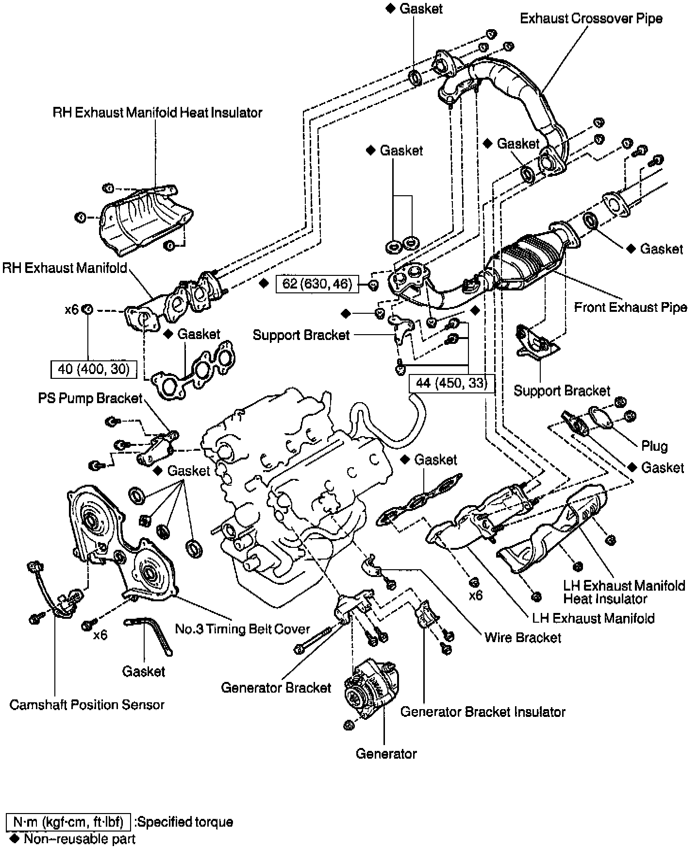
11. INSTALL EXHAUST MANIFOLDS
a. Install 2 new gaskets and the exhaust manifolds with the 12 nuts.
Torque: 40 Nm (30 ft. lbs.)

b. Install the exhaust manifold heat insulators with the 6 nuts.
Torque: 8 Nm (71 inch lbs.)
12. INSTALL EXHAUST CROSSOVER PIPE

Install 2 new gaskets and the crossover pipe with the 6 nuts.
Torque: 45 Nm (33 ft. lbs.)
13. INSTALL PS PUMP BRACKET
Torque: 18.5 Nm (14 ft. lbs.)
14. INSTALL GENERATOR BRACKET
Torque: 18.5 Nm (14 ft. lbs.)
15. INSTALL GENERATOR
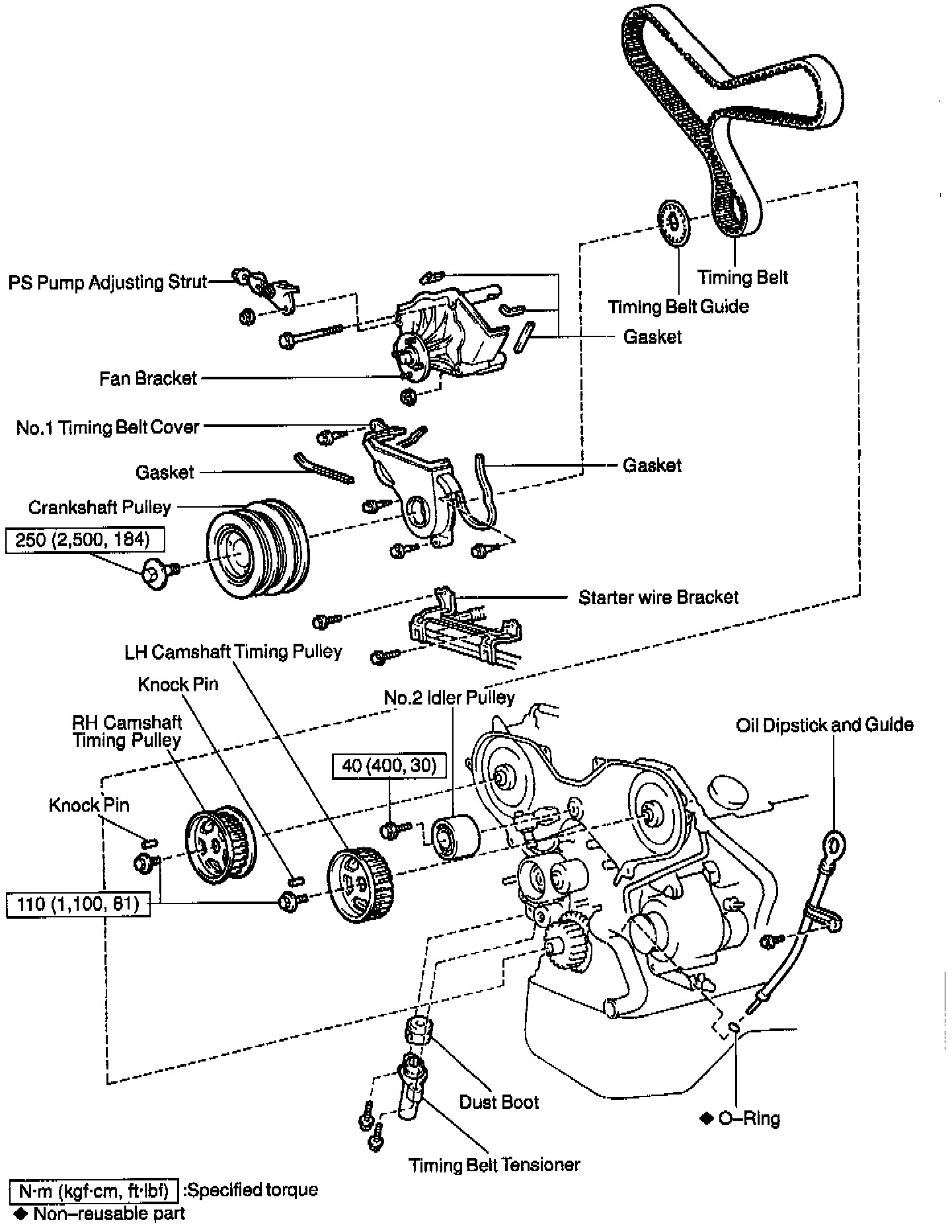
16. INSTALL NO.3 TIMING BELT COVER
a. Check that the timing belt cover gaskets have no cracks or peeling, etc.
If the gaskets have cracks or peeling etc., replace them using these steps:
- Using a screwdriver and gasket scraper, remove all the old gasket material.
- Thoroughly clean all components to remove all the loose material.

- Remove the backing paper from a new gasket and install the gasket evenly to the part of the timing belt cover shaded black in the illustration.
b. Install the timing belt cover with the 6 bolts.
Torque: 9 Nm (80 inch lbs.)

17. INSTALL CAMSHAFT POSITION SENSOR
a. Install the camshaft position sensor with the bolt.
Torque: 8 Nm (71 inch lbs.)
HINT: Match the protrusion of the sensor with the indentation of the RH cylinder head.
b. Connect the clamp to the No.3 timing belt cover.
c. Connect the camshaft position sensor connector.
18. INSTALL TIMING BELT
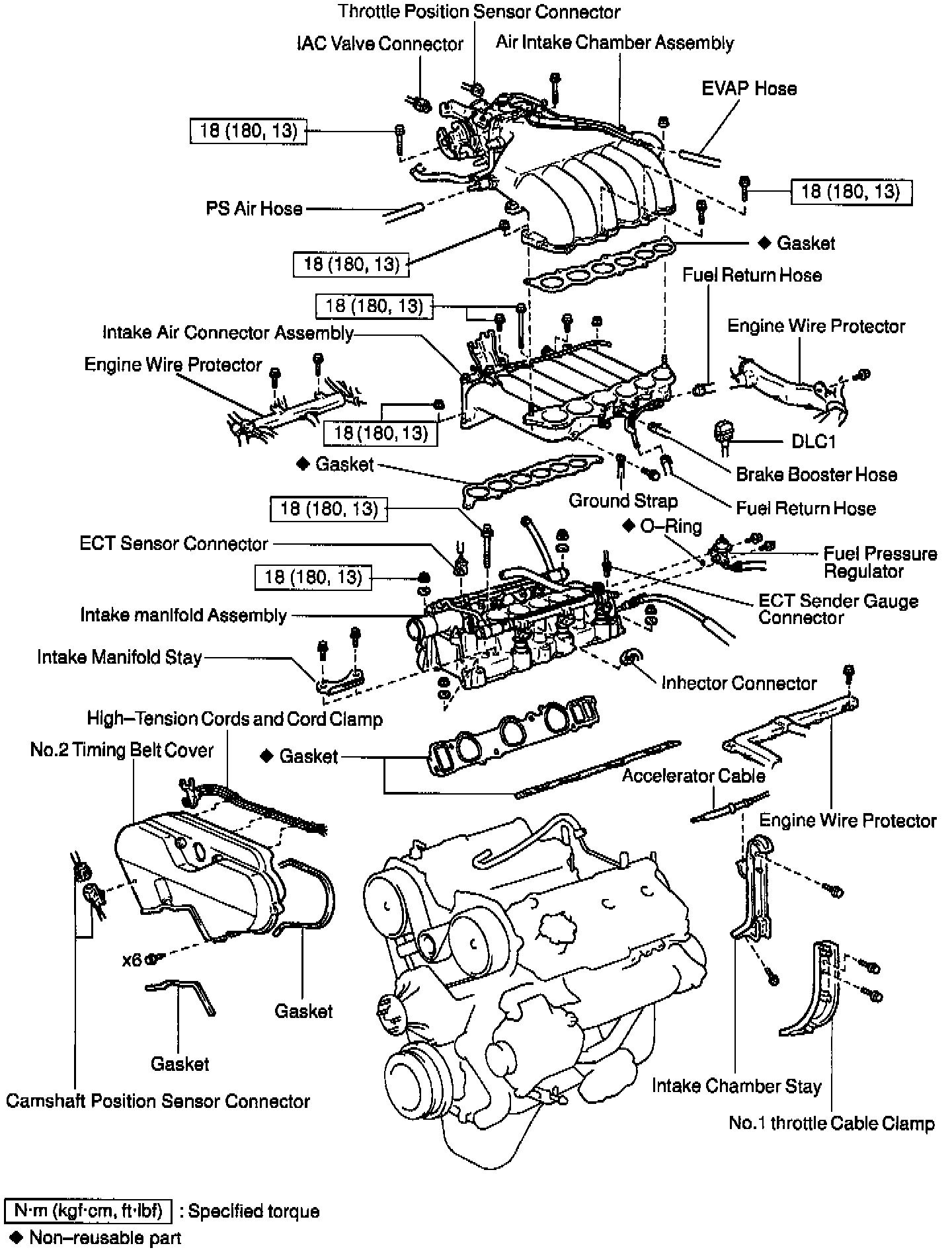
19. INSTALL INTAKE MANIFOLD ASSEMBLY

a. Install 2 new gaskets and the intake manifold, delivery pipe and injectors assembly with the 8 bolts, 4 plate washers and 4 nuts.
Torque: 18 Nm (13 ft. lbs.)
b. Install the intake manifold stay with the 2 bolts.
Torque: 18 Nm (13 ft. lbs.)
20. INSTALL FUEL PRESSURE REGULATOR
21. CONNECT ENGINE WIRE PROTECTOR

a. Connect the 2 engine wire clamp.

b. Install the engine wire with the 3 bolts.
c. Connect the 2 engine wire clamps.
d. Connect these connectors:
1) 6 injector connectors
2) Engine Coolant Temperature (ECT) sensor connector
3) ECT sender gauge connector
22. INSTALL INTAKE AIR CONNECTOR

a. Install a new gasket and the intake air connector with the 3 bolts and 2 nuts.
Torque: 18 Nm (13 ft. lbs.)

b. Connect the DLC1 to the bracket.
c. Install the ground strap to the intake air connector with the bolt.
d. Connect these hoses:
1) Fuel return hose
2) Vacuum hose to the fuel pressure regulator
e. Install the engine Afire with the bolt.
23. INSTALL AIR INTAKE CHAMBER ASSEMBLY

a. Install a new gasket and the air intake chamber assembly with the 4 bolts and 2 nuts.
Torque: 18 Nm (13 ft. lbs.)

b. Connect these hoses and these connectors:
1) Throttle position sensor connector
2) Idle Air Control (IAC) valve connector
3) 2 PCV hoses
4) 2 water bypass hoses
5) Air assist hose to throttle body
24. INSTALL NO.2 TIMING BELT COVER
25. INSTALL AIR INTAKE CHAMBER STAY
a. Install the air intake chamber stay with the 2 bolts.
Torque: 40 Nm (30 ft. lbs.)
b. Install the No.1 throttle cable clamp with the 2 bolts.
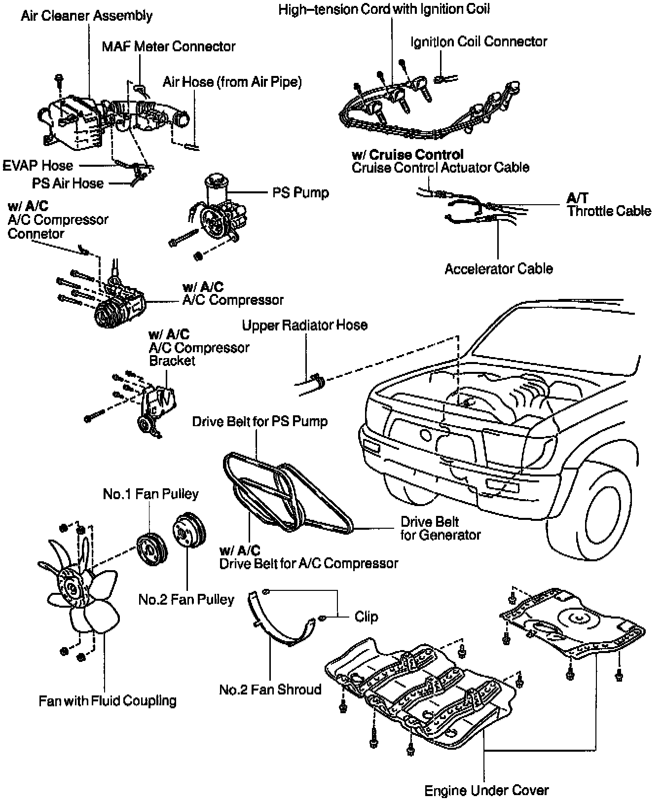
26. CONNECT HOSES
Connect these hoses:
- Fuel return hose
- Fuel inlet hose
- Brake booster vacuum hose
- Evaporative Emission (EVAP) hose
- (4WD only): A.D.D. Vacuum hose
27. CONNECT CABLES
Connect these cables:
- (A/T): Throttle cable
- Accelerator cable
- (w/ Cruise control): Cruise control actuator cable
28. INSTALL SPARK PLUGS AND HIGH-TENSION CORDS WITH IGNITION COILS
29. CONNECT HEATER HOSE
30. INSTALL AIR CLEANER ASSEMBLY
31. INSTALL FRONT EXHAUST PIPE
32. FILL WITH ENGINE COOLANT
33. START ENGINE AND CHECK FOR LEAKS
34. CHECK IGNITION TIMING
35. INSTALL ENGINE UNDER COVER
36. PERFORM ROAD TEST
Check for abnormal noise, shock, slippage, correct shift points and smooth operation.
37. RECHECK ENGINE COOLANT LEVEL