Alignment: Service and Repair
NOTICE: For Zero Point Calibration information, please refer to: TSB T-SB-0020-8 (3/25/08).INSPECTION
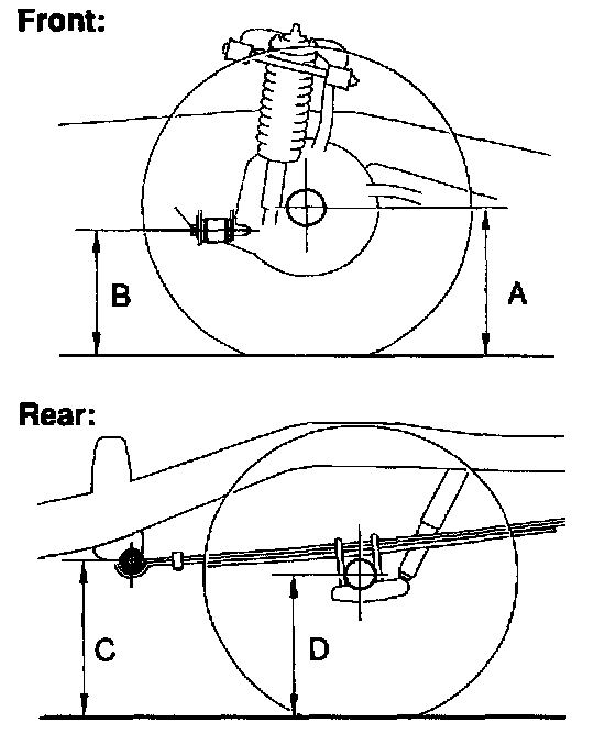
1. MEASURE VEHICLE HEIGHT
Measuring points:
A: Ground clearance of the front drive shaft center
B: Ground clearance of the front adjusting cam bolt center
C: Ground clearance of the leaf spring front side bushing center
D: Ground clearance of the rear axle shaft center Vehicle height:
Front: A - B
Rear: C - D
NOTICE: Before inspecting the wheel alignment, adjust the vehicle height to the specified value.
If the vehicle height is not the specified value, try to adjust it by pushing down on or lifting the body.
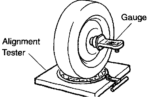
2. INSTALL CAMBER-CASTER-KINGPIN GAUGE OR POSITION VEHICLE ON WHEEL ALIGNMENT TESTER
Follow the specific instructions of the equipment manufacturer.
3. INSPECT CAMBER, CASTER AND STEERING AXIS INCLINATION
If the steering axis inclination is not within the specified value, after the camber and caster have been correctly adjusted, recheck the steering knuckle and front wheel for bearing or looseness.
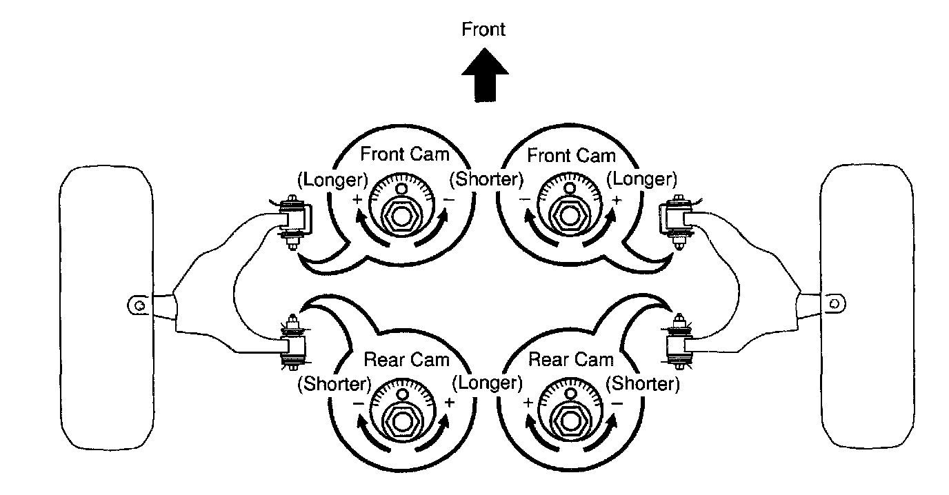
4. ADJUST CAMBER AND CASTER
a. Loosen the front and/or rear adjusting cam set bolts.
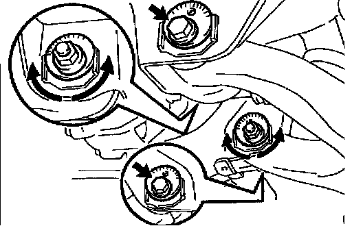
b. Adjust the camber and caster by front and/or rear adjusting cams (See adjustment chart).
HINT: Try to adjust the camber and caster to the center of the specified values.
c. How to read adjustment chart (Example).
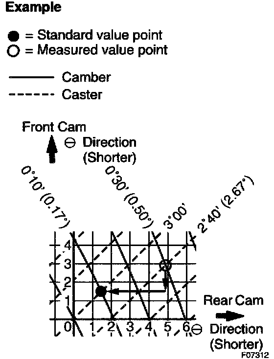
1. Find the applicable wheel alignment standard value for the particular model.
2. Mark the selected standard value on the adjustment chart.
Example:
Camber: 0°10'(0.17°)
Caster: 3°00'
3. Measure the present wheel alignment value with the vehicle in non-loaded condition.
4. Mark the measured present value on the adjustment chart.
Example:
Camber: 0°30' (0.50°)
Caster: 2°40' (2.670)
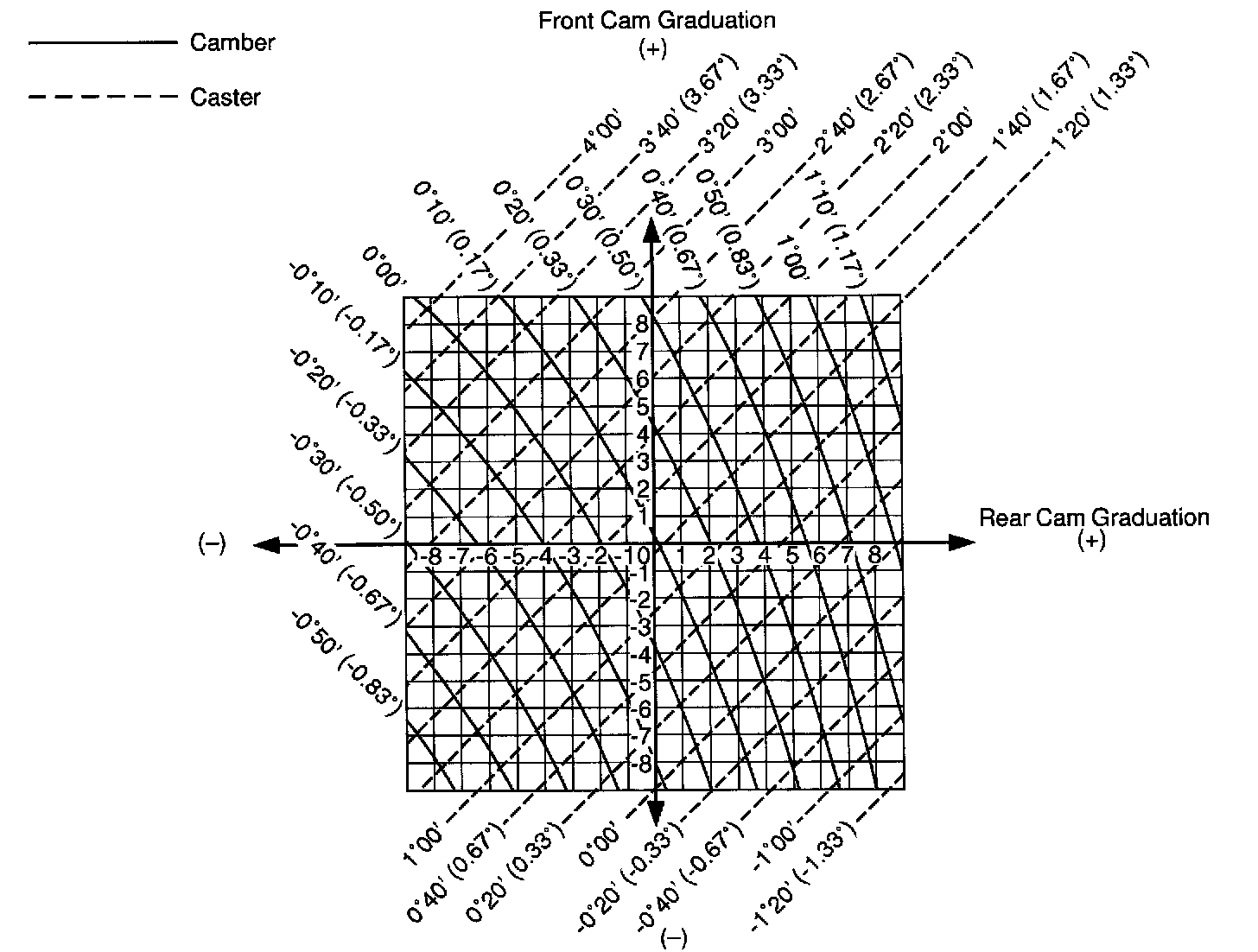
5. As shown in the example chart, read the distance from the measured value to the standard value, and adjust the front and/or rear adjusting cams accordingly.
Amount to turn adjusting cams (by graduation):
Example:
Front cam: - (Shorter) 1.3
Rear cam: - (Shorter) 3.3
d. Torque the front and/or rear adjusting cam set bolts.
Torque: 130 Nm (1,325 kgf-cm, 96 ft. lbs.)
Measuring Point Reference:
5. INSPECT TOE-IN
If the toe-in is not within the specified value, adjust the rack ends.
6. ADJUST TOE-IN AND WHEEL ANGLE
a. Remove the 2 clips.
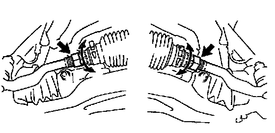
b. Loosen the tie rod end lock nuts.
c. Turn the right and left rack ends by an equal amount to adjust the toe-in.
HINT: Try to adjust the toe-in to the center of the specified value.
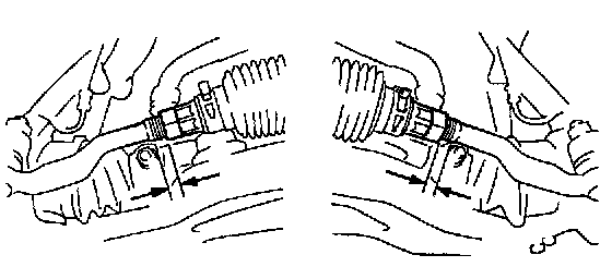
d. Make sure that the lengths of the right and left rack ends are the same.
Rack end length difference: 1.5 mm (0.059 inch) or less
e. Tighten the tie rod end lock nuts.
Torque: 55 Nm (560 kgf-cm, 41 ft. lbs.)
f. Place the boots on the seats and install the clips.
HINT: Make sure that the boots are not twisted.
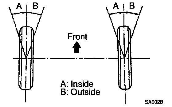
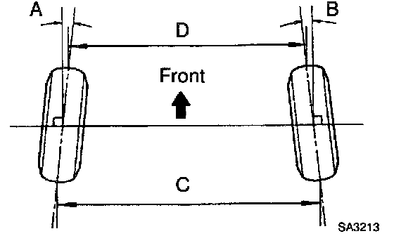
g. Inspect the wheel angle.
Turn the steering wheel fully and measure the turning angle.
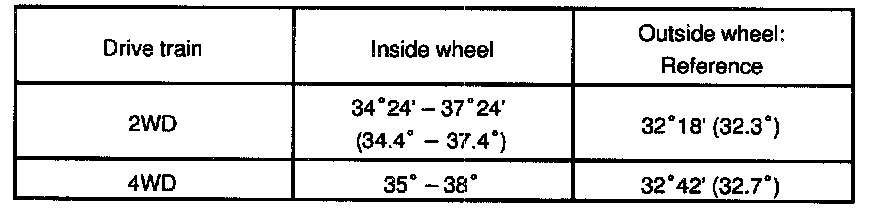
Wheel Turning Angle:
If the right and left wheel turning angles differ from the specified value, readjust the toe-in and wheel angle within the specified value. At this time, make sure that the lengths of the right and left rack ends are the same.
Rack end length difference: 1.5 mm (0.059 inch) or less