Key to Diagrams
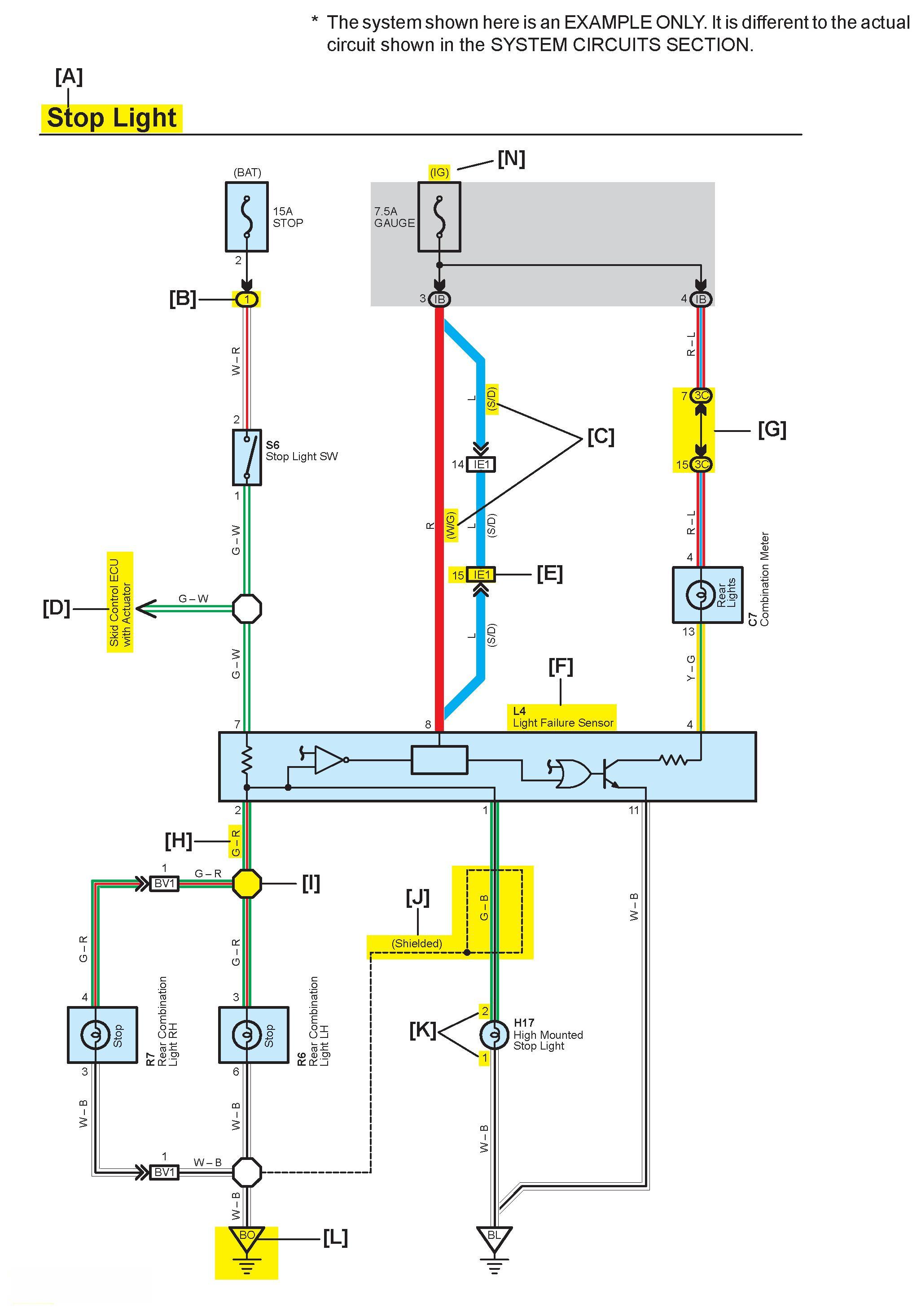
[A]: System Title
[B]: Indicates a Relay Block. No shading is used and only the Relay Block No. is shown to distinguish it from the J/B
Example: (1) Indicates Relay Block No.1
[C]: ( ) is used to indicate different wiring and connector, etc. when the vehicle model, engine type, or specification is different.
[D]: Indicates related system.
[E]: Indicates the wiring harness and wiring harness connector. The wiring harness with male terminal is shown with arrows.
Outside numerals are pin numbers.
The first letter of the code for each wiring harness and wiring harness connector(s) indicates the component's location, e.g, "E" for the Engine Compartment, "I" for the Instrument Panel and Surrounding area, and "B" for the Body and Surrounding area.
When more than one code has the first and second letters in common, followed by numbers (e.g, IH1, IH2), this indicates the same type of wiring harness and wiring harness connector.
[F]: Represents a part (all parts are shown in sky blue). The code is the same as the code used in parts position.
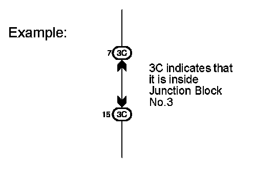
[G]: Junction Block (The number in the circle is the J/B No. and the connector code is shown beside it). Junction Blocks are shaded to clearly separate them from other parts.
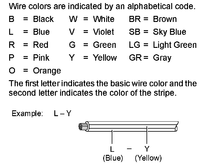
[H]: Indicates the wiring color.

[I]: Indicates a Splice Point.
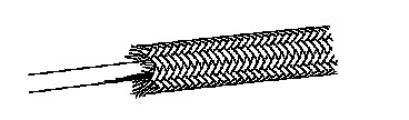
[J]: Indicates a shielded cable.
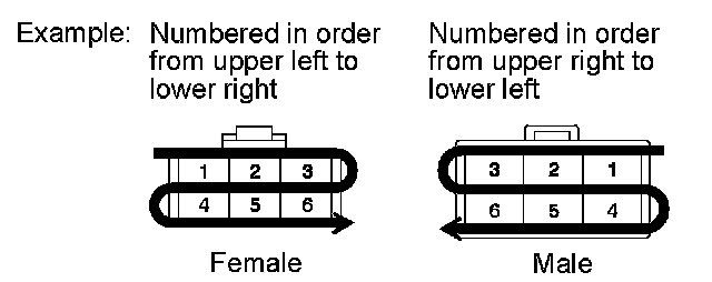
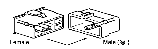
[K]: Indicates the pin number of the connector.
The numbering system is different for female and male connectors.
[L]: Indicates the ground point.
The first letter of the code for each ground point(s) indicates the component's location, e.g, "E" for the Engine Compartment, "I" for the Instrument Panel and Surrounding area, and "B" for the Body and Surrounding area.
[M]: Page No.
[N]: Indicates the ignition key position(s) when the power is supplied to the fuse(s).
[O]: System Outline
Current is applied at all times through the STOP fuse to TERMINAL 2 of the stop lamp SW. When the ignition SW is turned on, current flows from the GAUGE fuse to TERMINAL 8 of the light failure sensor, and also flows through the rear lights warning light to TERMINAL 4 of the light failure sensor.
Stop Light Disconnection Warning
When the ignition SW is turned on and the brake pedal is pressed (Stop lamp SW on), if the stop light circuit is open, the current flowing from TERMINAL 7 of the light failure sensor to TERMINALS 1, 2 changes, so the light failure sensor detects the disconnection and the warning circuit of the light failure sensor is activated.
As a result, the current flows from TERMINAL 4 of the light failure sensor to TERMINAL 11 to GROUND and turns the rear lights warning light on. By pressing the brake pedal, the current flowing to TERMINAL 8 of the light failure sensor keeps the warning circuit on and holds the warning light on until the ignition SW is turned off.
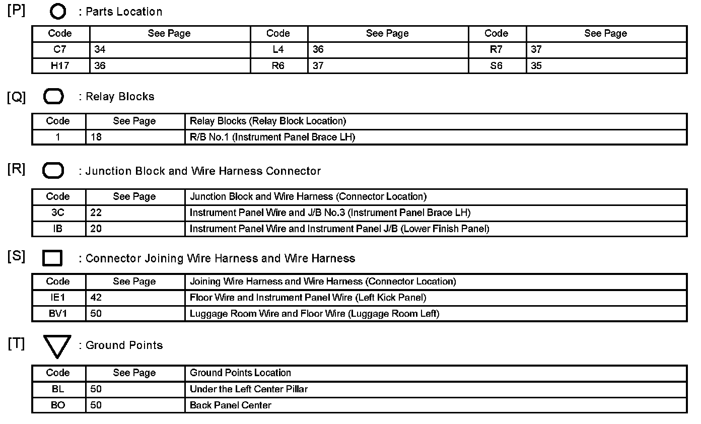
Diagram Legend
[O]: Explains the system outline.
[P]: Indicates the reference page showing the position on the vehicle of the parts in the system circuit.
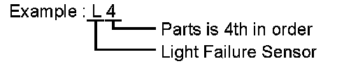
Example : Part "L4" (Light Failure Sensor).
- The letter in the code is from the first letter of the part, and the number indicates its order in parts starting with that letter.
[Q]: Indicates the reference page showing the position on the vehicle of Relay Block Connectors in the system circuit.
Example : Connector "1" is described and is installed on the left side of the instrument panel.
[R]: Indicates the reference page showing the position on the vehicle of J/B and Wire Harness in the system circuit.
Example : Connector "3C" connects the Instrument Panel Wire and J/B No.3. It is described and is installed on the instrument panel left side.
[S]: Indicates the reference page describing the wiring harness and wiring harness connector (the female wiring harness is shown first, followed by the male wiring harness).
Example : Connector "IE1" connects the floor wire (female) and Instrument panel wire (male). It is described and is installed on the left side kick panel.
[T]: Indicates the reference page showing the position of the ground points on the vehicle.
Example : Ground point "BO" is described and is installed on the back panel center.