Only Wireless Control Function Is Inoperative
DOOR LOCK: WIRELESS DOOR LOCK CONTROL SYSTEM: Only Wireless Control Function is Inoperative
Only Wireless Control Function is Inoperative
DESCRIPTION
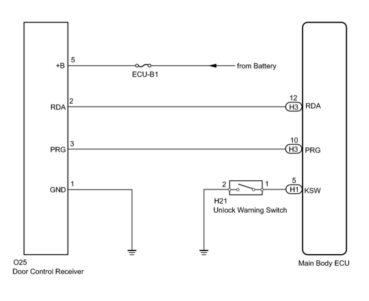
The door control receiver receives signals from the transmitter and sends these signals to the main body ECU. The main body ECU then controls all doors by sending lock/unlock signals to each door, and sends hazard flasher relay signals to the turn signal flasher relay (hazard warning lights).
WIRING DIAGRAM
INSPECTION PROCEDURE
PROCEDURE
1. CHECK WIRELESS DOOR LOCK CONTROL FUNCTIONS
(a) Check the wireless door lock control system function Operation Check.
Result

B -- GO TO POWER BACK DOOR SYSTEM
A -- Continue to next step.
2. CHECK DOOR CONTROL TRANSMITTER
(a) When another registered door control transmitter is used, check that the wireless operates normally.
Result
B -- CHECK ROOM LIGHT ASSEMBLY
A -- Continue to next step.
3. INSPECT TRANSMITTER BATTERY (VOLTAGE)
(a) Electrical key transmitter
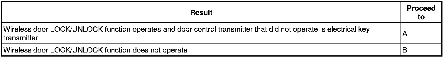
(1) Remove the battery from the electrical key transmitter that does not operate. Attach a lead wire (0.6 mm (0.0236 in.) in diameter or less including wire sheath) with tape or equivalent to the negative terminal Service and Repair.
NOTE: Do not wrap the lead wire around a terminal, wedge it between terminals, or solder it. A terminal may be deformed or damaged, and the battery will not be able to be installed correctly.
(2) Carefully pull the lead wire out from the position shown in the illustration and install the previously removed transmitter battery.
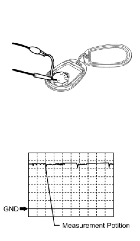
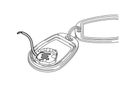
(3) Using an oscilloscope, check the transmitter battery voltage waveform.
HINT: Measure the transmitter battery voltage while pressing the LOCK or UNLOCK switch on the transmitter.
Standard Voltage:
NG -- REPLACE TRANSMITTER BATTERY
OK -- REPLACE DOOR CONTROL TRANSMITTER
4. CHECK ROOM LIGHT ASSEMBLY
(a) Check that the room light illumination operates normally.
OK:
Room light operation normally.
NG -- Go to LIGHTING SYSTEM
OK -- Continue to next step.
5. SWITCH TO SELF-DIAGNOSTIC MODE
(a) Switch to self-diagnostic mode by operating the ignition key cylinder.
(1) Make sure the vehicle is in its initial condition. Then insert the key into the ignition key cylinder and remove it.
(2) Within 5 seconds of removing the key, insert the key into the ignition key cylinder (ignition switch off). Then turn the ignition switch to ON and off.
(3) Within 30 seconds of turning the ignition switch off, perform the following operation 9 times: turn the ignition switch to ON and then off.
NOTE: If the system cannot enter self-diagnostic mode, the system returns to normal mode.
- Turning the ignition switch to ON after the above operations have been completed ends self-diagnostic mode.
- Do not lock or unlock doors during self-diagnostic mode.
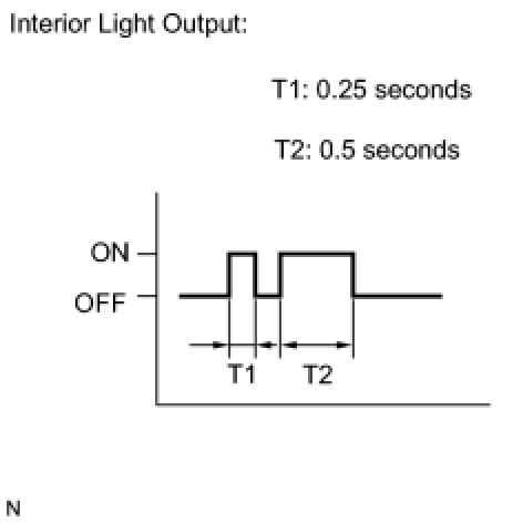
(b) Check that the system has switched to self-diagnostic mode by checking the room light flash pattern.
OK:
Flash pattern is same as illustration.
NG -- INSPECT UNLOCK WARNING SWITCH
OK -- Continue to next step.
6. CHECK BY SELF DIAGNOSTIC MODE
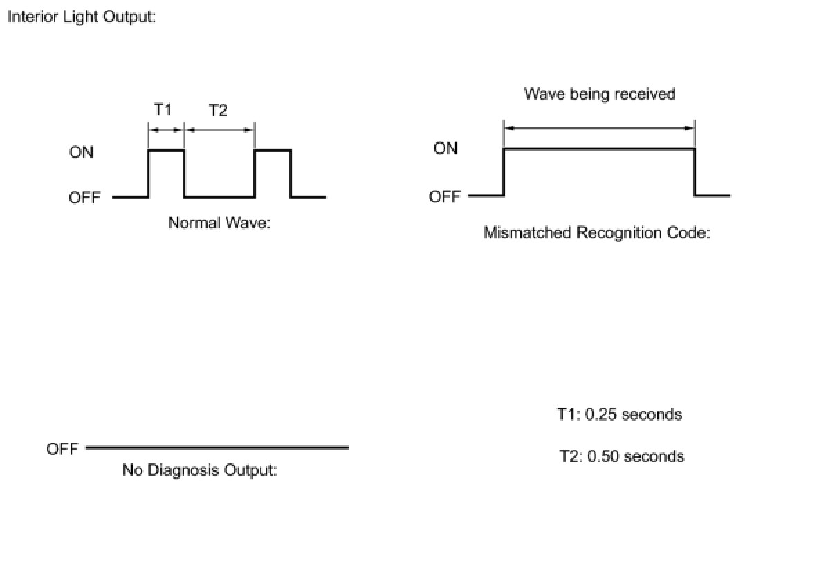
(a) Inspect the diagnosis outputs when the door control transmitter switch is held down. The diagnosis outputs can be checked by the flash patterns of the room light.
Result
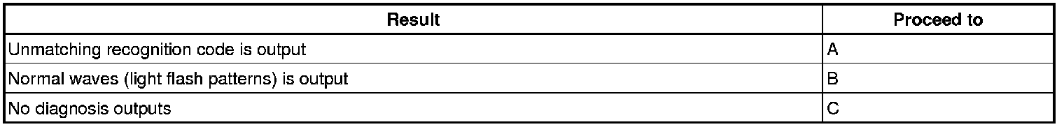
C -- CHECK DOOR CONTROL RECEIVER (RESPONSE)
B -- REPLACE MAIN BODY ECU
A -- Continue to next step.
7. REGISTER RECOGNITION CODE
(a) Check that the system can be switched to rewrite mode or add mode, and that a recognition code can be registered Registration.
OK:
Recognition code can be registered.
NG -- REPLACE DOOR CONTROL TRANSMITTER
OK -- END
8. CHECK DOOR CONTROL RECEIVER (RESPONSE)
(a) Prepare the door control transmitter of another vehicle.
(b) Hold down the door control transmitter switch.
(c) Check that an unmatching recognition code is output.
OK:
Unmatching recognition code is output.
NG -- REPLACE DOOR CONTROL RECEIVER
OK -- REPLACE DOOR CONTROL TRANSMITTER
9. REPLACE DOOR CONTROL RECEIVER
(a) Temporarily replace the door lock control receiver with a new or normally functioning one Removal.
NEXT -- Continue to next step.
10. REGISTER RECOGNITION CODE
(a) Perform the registration procedures Registration.
NEXT -- Continue to next step.
11. CHECK DOOR CONTROL RECEIVER (OPERATION)
(a) Check that the doors can be locked and unlocked by using the transmitter LOCK and UNLOCK switches.
OK:
Doors can be locked and unlocked with transmitter.
NG -- REPLACE MAIN BODY ECU
OK -- END (DOOR CONTROL RECEIVER IS DEFECTIVE)
12. INSPECT UNLOCK WARNING SWITCH
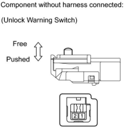
(a) Remove the unlock warning switch Removal.
(b) Measure the resistance according to the value(s) in the table below.
Standard Resistance:

(c) Reconnect the unlock warning switch.
NG -- REPLACE UNLOCK WARNING SWITCH
OK -- Continue to next step.
13. CHECK HARNESS AND CONNECTOR (UNLOCK WARNING SWITCH - MAIN BODY ECU AND BODY GROUND)
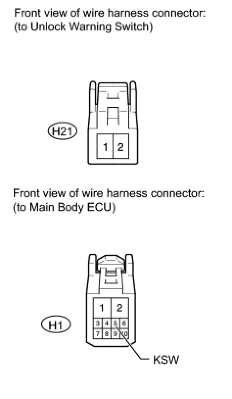
(a) Disconnect the H21 unlock warning switch connector.
(b) Disconnect the H1 main body ECU connector.
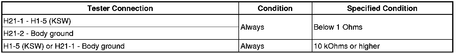
(c) Measure the resistance according to the value(s) in the table below.
Standard Resistance:
(d) Reconnect the unlock warning switch connector.
(e) Reconnect the main body ECU connector
NG -- REPAIR OR REPLACE HARNESS OR CONNECTOR
OK -- Continue to next step.
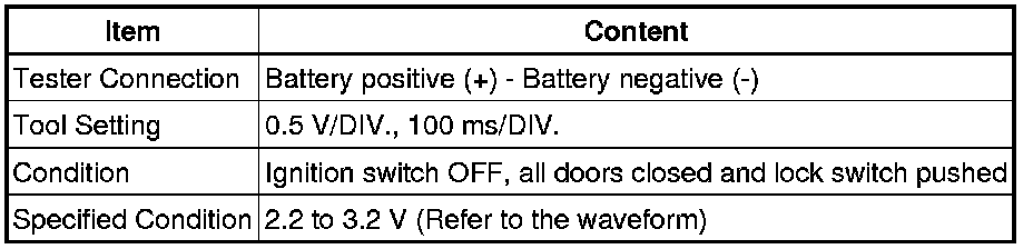
14. INSPECT DOOR CONTROL RECEIVER (OUTPUT)
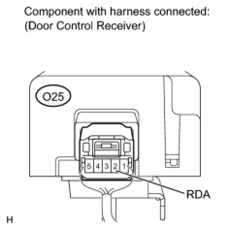
(a) Measure the voltage according to the value(s) in the table below.
Standard Voltage:

NG -- REPLACE DOOR CONTROL TRANSMITTER
OK -- REPLACE MAIN BODY ECU
15. REPLACE DOOR CONTROL TRANSMITTER
(a) Temporarily replace the door control transmitter module with a new or normally functioning one.
NEXT -- Continue to next step.
16. REGISTER RECOGNITION CODE
(a) Perform the registration procedures Registration.
NEXT -- Continue to next step.
17. CHECK DOOR CONTROL TRANSMITTER MODULE
(a) Check that the doors can be locked and unlocked by using the transmitter LOCK and UNLOCK switches.
OK:
Doors can be locked and unlocked with transmitter.
NG -- REPLACE DOOR CONTROL RECEIVER
OK -- END (DOOR CONTROL TRANSMITTER MODULE IS DEFECTIVE)