Front
WHEEL ALIGNMENT1. Measure vehicle height.
Tire size: 215/70R16
Front: 237 mm (9.33 inch)
Rear: 360 mm (14.17 inch)
Front:

Front measuring point: Measure from the ground to the center of the lower suspension arm front mounting bolt.
Rear:

Rear measuring point: Measure from the ground to the center of the body side No. 1 suspension arm mounting bolt.
NOTICE: Before inspecting the wheel alignment, adjust the vehicle height to the specification.
If the vehicle height is not to specification, try to adjust it by pushing down on or lifting the body.
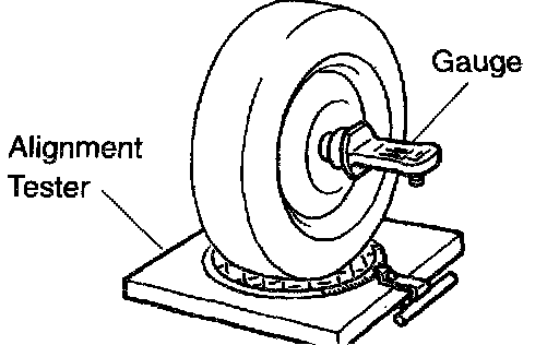
2. Install camber-caster-kingpin gauge onto vehicle or position vehicle on wheel alignment tester.
Follow the specific instructions of the equipment manufacturer.
3. Inspect camber, caster and steering axis inclination.
Tire size: 215/70R16
Camber: -0° 15' ± 45' (-0.25° ± 0.75°)
Left-Right error: 45' (0.75°) or less
Caster: 1° 20' ± 45' (1.33° ± 0.75°)
Left-Right error: 45' (0.75°) or less
Steering axis inclination: 10° 45' ± 45' (10.75° ± 0.75°)
Left-Right error: 45' (0.75°) or less
If the caster and steering axis inclination are not within the specification, after the camber has correctly adjusted, recheck the suspension parts for damaged and/or worn out parts.
Measuring Point Reference:
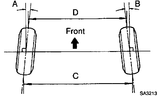
4. Inspect toe-in.
Toe-in (total):
A + B: 0° ± 0° 10' (0° ± 0.17°)
C - D: 0 ± 2 mm (0 ± 0.08 inch)
If the toe-in is not within the specification, adjust it by the tie rod end.
5. Adjust camber.
NOTICE: After the camber has been adjusted, inspect the toe-in.
a. Remove the front wheels.

b. Remove the 2 nuts on the lower side of the shock absorber.
c. Coat the threads of the nuts with engine oil.
d. Temporarily install the 2 nuts.

e. Adjust the camber by pushing or pulling the lower side of the shock absorber in the direction in which the camber adjustment is required.

f. Tighten the 2 nuts.
Torque: 158 Nm (117 ft. lbs.)
g. Install the front wheels.
Torque: 103 Nm (76 ft. lbs.)
h. Check the camber.
HINT:
^ Try to adjust the camber to the center value.
^ Adjusting value for the set bolts is 6' - 30' (0.1° - 0.5°).

If the camber is not within the specification, using the table, estimate of how much additional camber adjustment will be required, and select the camber adjusting bolt.
i. Do the above mention steps again. Between the step b. and c., exchange (1 or 2) selected bolts.
HINT: When exchange 2 bolts, exchange 1 bolt or each time.
6. Adjust toe-in.
a. Remove the boot clamps.
b. Loosen the tie rod end lock nuts.

c. Turn the left and right rack ends an equal amount to adjust the toe-in.

HINT:
^ Try to adjust the toe-in to the center value.
^ Make sure that the length of the left and right rack ends is the same.
Tie rod end length difference: 1.5 mm (0.059 inch) or less
d. Torque the tie rod end lock nuts.
Torque: 56 Nm (41 ft. lbs.)
e. Place the boot on the seat and install the clamp.
HINT: Make sure that the boots are not twisted.
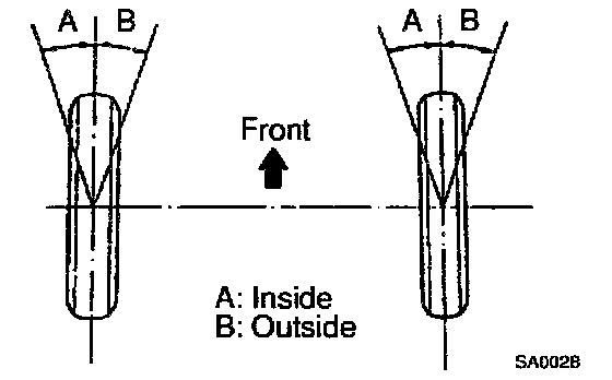
7. Inspect wheel angle. Turn the steering wheel fully, and measure the turning angle.
Inside wheel: 33° 15' ± 2°
Outside wheel: 28° 05' (reference)
If the wheel angles differ from the standard specification, adjust the toe-in.