Removal and Installation
REMOVAL
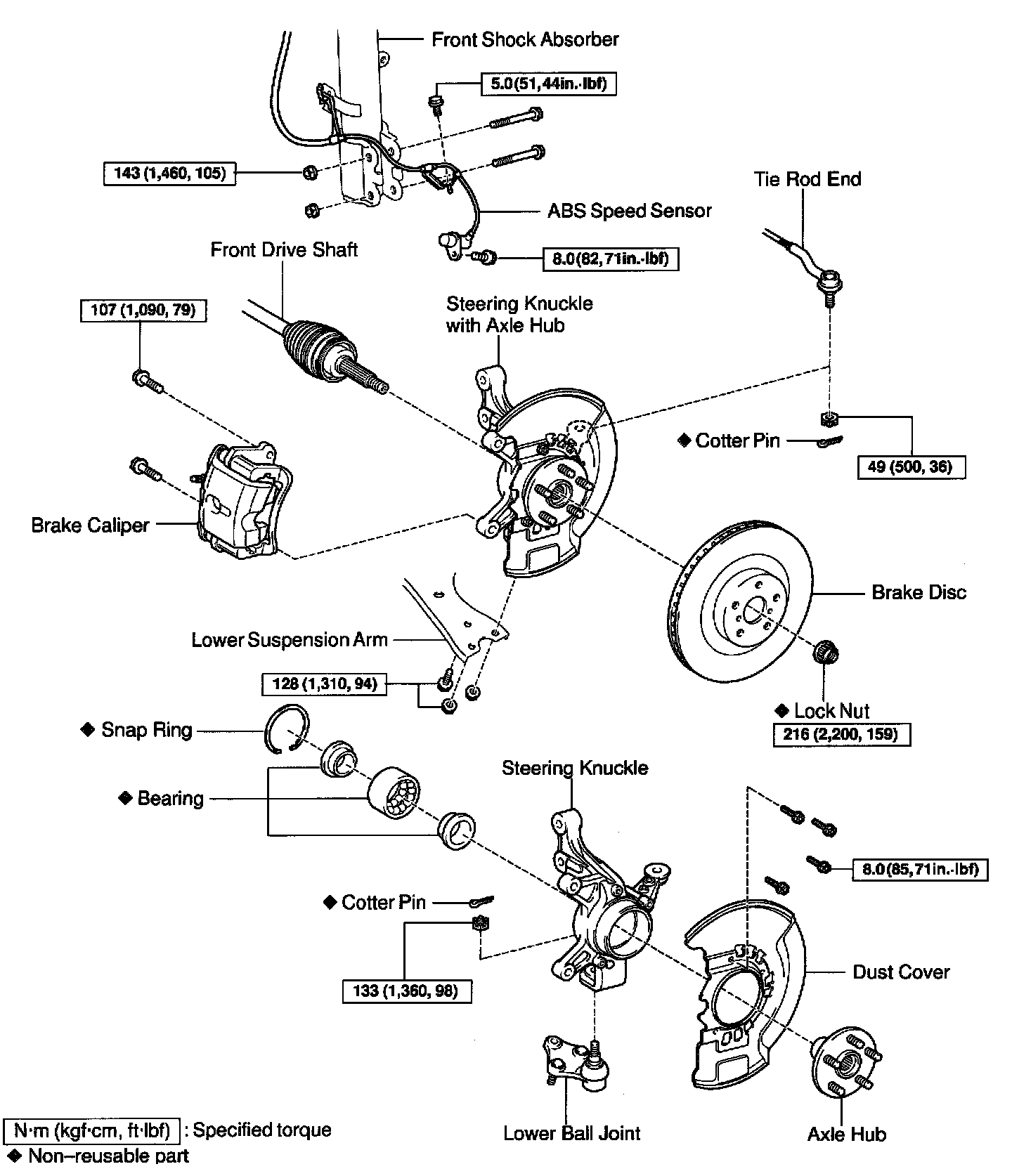
1. REMOVE FRONT WHEEL

2. REMOVE BRAKE CALIPER AND DISC
a. Remove the 2 bolts, and disconnect the brake caliper.
Torque: 107 Nm (1,090 kgf-cm, 79 ft. lbs.)
b. Support the brake caliper securely.
NOTICE: Do not damage the flexible hose.
c. Remove the brake disc.

3. CHECK BEARING BACKLASH AND AXLE HUB DEVIATION
a. Set a dial indicator near the center of the axle hub.
b. Check the backlash.
Maximum: 0.05 mm (0.0020 inch)
If it is greater than maximum, replace the bearing.
c. Check the deviation.
Maximum: 0.07 mm (0.0028 inch)
If it is greater than maximum, replace the bearing.
d. Remove a dial indicator.
4. REMOVE DRIVE SHAFT LOCK NUT
5. w/ ABS:
DISCONNECT ABS SPEED SENSOR Remove the 2 bolts, and disconnect the ABS speed sensor and wire from the steering knuckle.
Torque:
Sensor installation bolt: 8.0 Nm (82 kgf-cm, 71 inch lbs.)
Wire harness clamp bolt: 5.0 Nm (51 kgf-cm, 44 inch lbs.)
6. REMOVE STEERING KNUCKLE WITH AXLE HUB

a. Loosen the 2 nuts of the lower side of the shock absorber.
Torque: 143 Nm (1,460 kgf-cm, 105 ft. lbs.)

b. Disconnect the tie rod end from the steering knuckle.
1. Remove the cotter pin and nut.
Torque: 49 Nm (500 kgf-cm, 36 ft. lbs.)
2. Using SST, disconnect the tie rod end from the steering knuckle.
SST 09610-20012

c. Remove the bolt and 2 nuts, and disconnect the lower ball joint from the lower suspension arm.
Torque: 128 Nm (1,310 kgf-cm, 94 ft. lbs.)
d. Disconnect the drive shaft from the steering knuckle.
e. Remove the 2 bolts, 2 nuts and steering knuckle with axle hub.
HINT: At the time of installation, coat the threads of the nuts with engine oil.
NOTICE: Be careful not to damage the ABS speed sensor rotor of the drive shaft.
INSTALLATION
Installation is in the reverse order of removal.
HINT: After installation, check the ABS speed sensor signal and front wheel alignment.