Automatic Transaxle Replacement
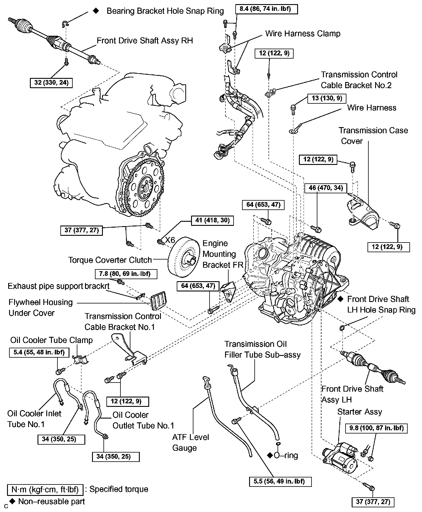
AUTOMATIC TRANSAXLE ASSY
REPLACEMENT
1. REMOVE ENGINE ASSEMBLY WITH TRANSAXLE
2. REMOVE FRONT DRIVE SHAFT ASSY RH
3. REMOVE FRONT DRIVE SHAFT ASSY LH
SST 09520-01010, 09520-24010 (09520-32040)
4. REMOVE TRANSMISSION CONTROL CABLE BRACKET NO.2
a) Remove the bolt and transmission control cable bracket No.2.
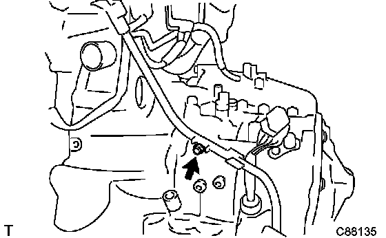
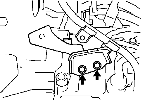
5. REMOVE WIRE HARNESS CLAMP
a) Disconnect the wire harnesses from the 2 clamps.
b) Remove the 2 bolts and 2 clamps.
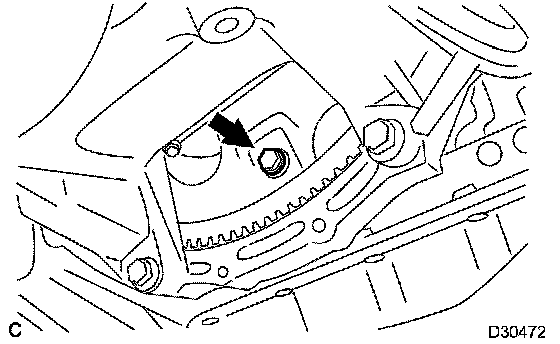
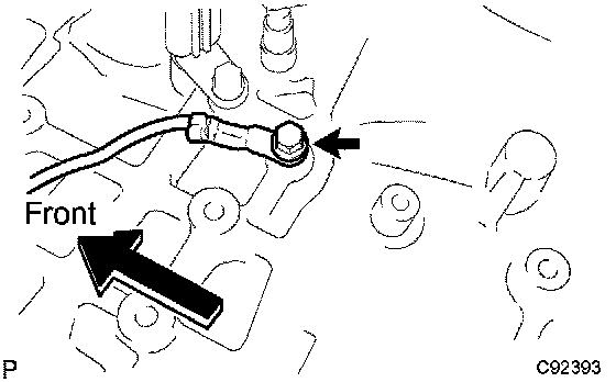
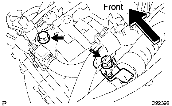
6. DISCONNECT WIRE HARNESS
a) Remove the bolt and disconnect the wire harness.
7. REMOVE STARTER ASSY
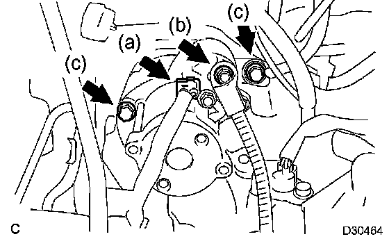
a) Disconnect the connector.
b) Remove the nut and disconnect the starter wire.
c) Remove the 2 bolts and starter assy.
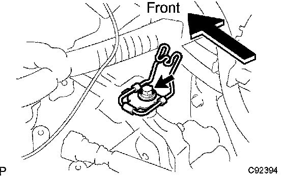
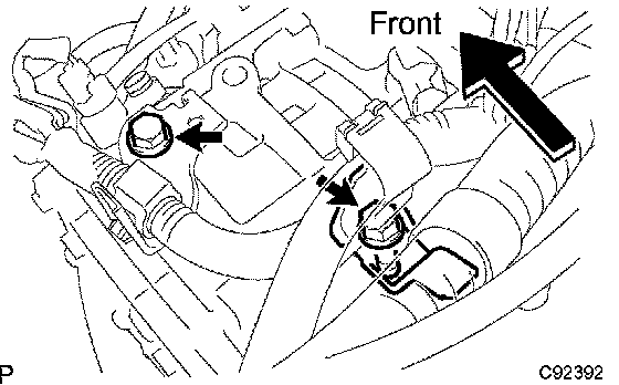
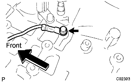
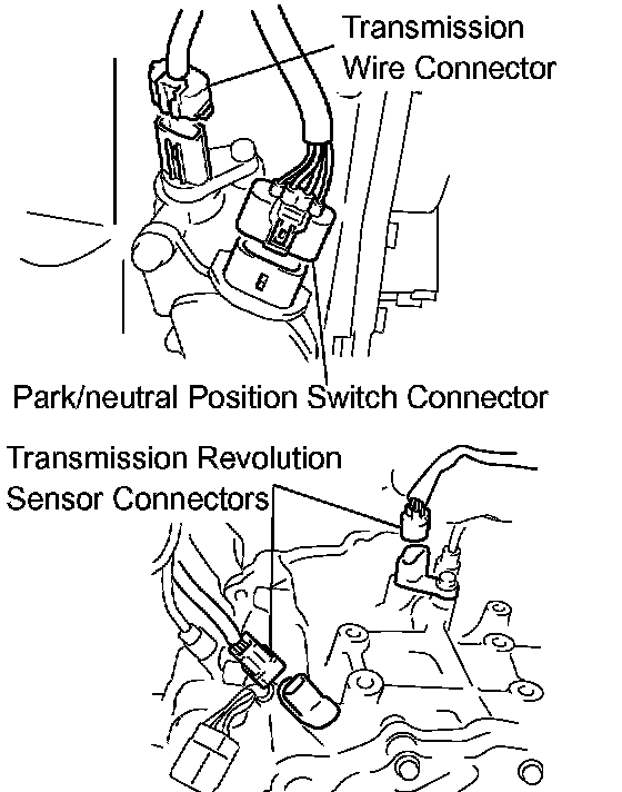
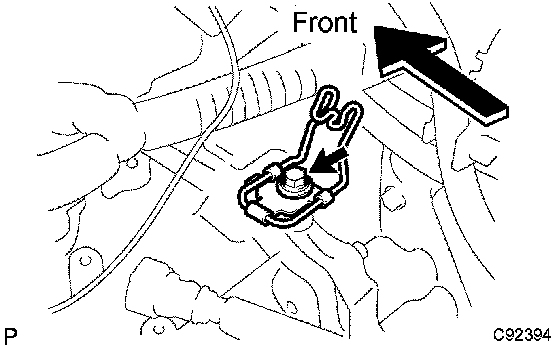
8. DISCONNECT CONNECTOR
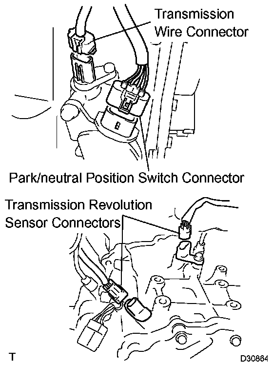
a) Disconnect the transmission wire connector.
b) Disconnect the park/neutral position switch connector.
c) Disconnect the 2 transmission revolution sensor connectors.
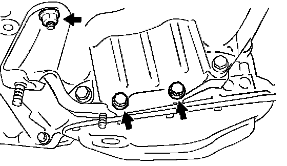
9. REMOVE TRANSMISSION CONTROL CABLE BRACKET NO.1
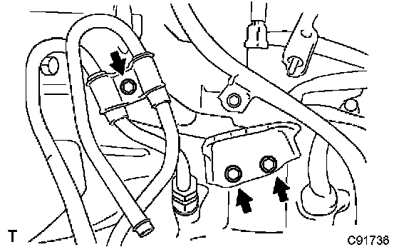
a) Remove the bolt and oil cooler tube clamp.
b) Remove the 2 bolts and transmission control cable bracket No.1.
10. REMOVE TRANSMISSION OIL FILLER TUBE SUB-ASSY
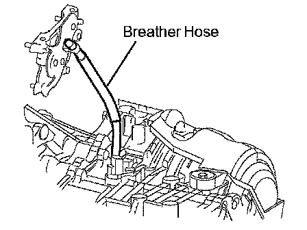
a) Remove the ATF level gauge.
b) Disconnect the breather hose from the wire harness bracket.
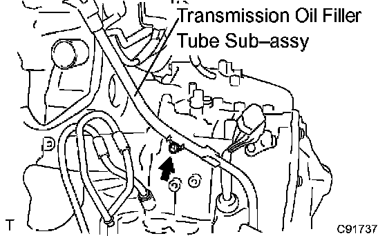
c) Remove the bolt and transmission oil filler tube sub-assy.
d) Remove the O-ring from the oil filler tube sub-assy.
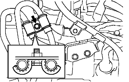
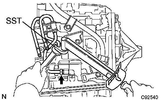
11. REMOVE OIL COOLER INLET TUBE NO.1

a) Using SST and a wrench, disconnect the oil cooler inlet tube No. 1.
SST 09023-12700
12. REMOVE OIL COOLER OUTLET TUBE NO.1
a) Using SST and a wrench, disconnect the oil cooler outlet tube No.1.
SST 09023-12700
13. REMOVE TRANSVERSE ENGINE ENGINE MOUNTING BRACKET
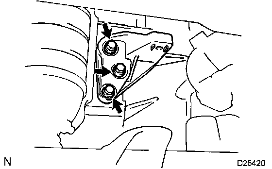
a) Remove the 3 bolts and engine mounting bracket FR.
14. REMOVE AUTOMATIC TRANSAXLE ASSY

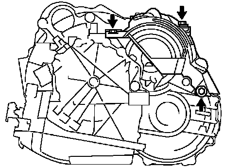
a) Remove the 2 bolts and nut.
b) Remove the exhaust pipe support bracket and exhaust pipe support bracket No.1 from the automatic transaxle.

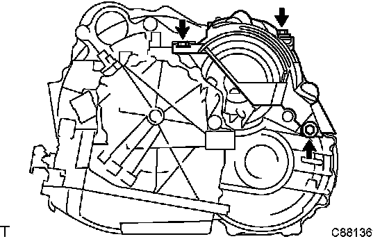
c) Turn the crankshaft to gain access and remove the 6 bolts while holding the crankshaft pulley bolt with a wrench.
HINT: There will be one green colored bolt.
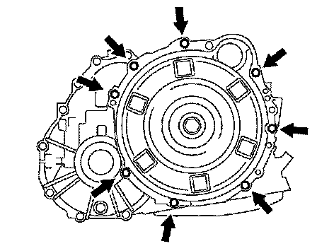
d) Remove the 8 bolts.
e) Separate and remove the automatic transaxle.
15. REMOVE TORQUE CONVERTER CLUTCH ASSY
16. REMOVE TRANSAXLE CASE COVER UPPER
a) Remove the 3 bolts and transmission case cover upper.
17. INSPECT TORQUE CONVERTER CLUTCH ASSY
SST 09350-32014 (09351-32010, 09351-32020)
18. INSTALL TRANSAXLE CASE COVER UPPER
a) Install the transmission case cover upper with the 3 bolts.
Torque: 12 Nm (122 kgf-cm, 9 ft. lbs.)
19. INSTALL TORQUE CONVERTER CLUTCH ASSY
a) Install the torque converter clutch to the automatic transaxle.
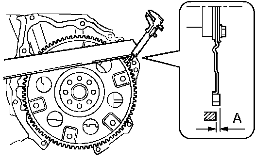
b) Using vernier calipers and a straight edge, measure the dimension "A" between the transaxle fitting part of the engine and the converter fitting part of the drive plate.
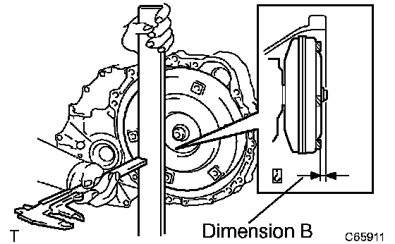
c) Using vernier calipers and a straight edge, measure the dimension "B" shown in the illustration and check that "B" is greater than "A" (measured in step (b)).
Standard: A + 1 (0.03937 inch) mm or more
NOTICE: Remember to minus the thickness of the straight edge.
20. INSTALL AUTOMATIC TRANSAXLE ASSY
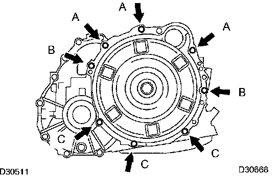
a) Install the automatic transaxle to the engine with the 8 bolts.
Torque:
Bolt A: 64 Nm (653 kgf-cm, 47 ft. lbs.)
Bolt B: 46 Nm (470 kgf-cm, 34 ft. lbs.)
Bolt C: 37 Nm (377 kgf-cm, 27 ft. lbs.)
b) Apply a few drops of adhesive to 2 threads on the tip of the 6 torque converter clutch mounting bolts.
Adhesive: Part No. 08833-00070, THREE BOND 1324 or equivalent
c) Install the 6 torque converter clutch mounting bolts.
Torque: 41 Nm (418 kgf-cm, 30 ft. lbs.)
NOTICE: First install the green colored bolt, and then the remaining 5 bolts.
d) Install the exhaust pipe support bracket and exhaust pipe support bracket No.1 to the automatic transaxle with the 2 bolts and nut.
Torque:
Bolt: 7.8 Nm (80 kgf-cm, 69 inch lbs.)
Nut: 21 Nm (214 kgf-cm, 16 ft. lbs.)
21. INSTALL TRANSVERSE ENGINE ENGINE MOUNTING BRACKET

a) Install the engine mounting bracket FR with the 3 bolts to the automatic transaxle.
Torque: 64 Nm (653 kgf-cm, 47 ft. lbs.)
22. INSTALL TRANSMISSION OIL FILLER TUBE SUB-ASSY
a) Coat a new O-ring with ATF, and install it to the oil filler tube.
b) Install the oil filler tube to the automatic transaxle with the bolt.
Torque: 5.5 Nm (56 kgf-cm, 49 inch lbs.)

c) Connect the breather hose to the wire harness bracket.
NOTICE: The breather hose should be on the left side of the vehicle.
d) Install the ATF level gauge.
23. INSTALL TRANSMISSION CONTROL CABLE BRACKET NO.1
a) Install the control cable bracket No.1 with the 2 bolts.
Torque: 12 Nm (122 kgf-cm, 9 ft. lbs.)
24. INSTALL OIL COOLER INLET TUBE NO.1
a) Temporarily install the oil cooler outlet tube No.1.
b) Temporarily install the oil cooler inlet tube No.1.
c) Install the oil cooler tube clamp and bolt.
Torque: 5.4 Nm (55 kgf-cm, 48 inch lbs.)
HINT: Install them so that the oil cooler tube cushion is positioned as shown in the illustration.
d) Using SST and a wrench, tighten the oil cooler inlet tube No. 1.
SST 09023-12700
Torque: 34 Nm (350 kgf-cm, 25 ft. lbs.)
25. INSTALL OIL COOLER OUTLET TUBE NO.1
a) Using SST and a wrench, tighten the oil cooler outlet tube No.1.
SST 09023-12700
26. CONNECT CONNECTOR
a) Connect the transmission wire connector.
b) Connect the park/neutral position switch connector.
c) Connect the 2 transmission revolution sensor connectors.
27. INSTALL STARTER ASSY

a) Install the starter assy with the 2 bolts.
Torque: 37 Nm (377 kgf-cm, 27 ft. lbs.)
b) Connect the connector.
c) Connect the starter wire with the nut.
Torque: 9.8 Nm (100 kgf-cm, 87 inch lbs.)
28. CONNECT WIRE HARNESS
a) Connect the wire harness with the bolt.
Torque: 13 Nm (139 kgf-cm, 9 ft. lbs.)
29. INSTALL WIRE HARNESS CLAMP
a) Install the 2 clamps and 2 bolts.
Torque: 8.4 Nm (86 kgf-cm, 74 inch lbs.)
b) Connect the wire harnesses to the clamps.
30. INSTALL TRANSMISSION CONTROL CABLE BRACKET NO.2
a) Install the transmission control cable bracket No.2 with the bolt.
Torque: 12 Nm (122 kgf-cm, 9 ft. lbs.)
31. INSTALL FRONT DRIVE SHAFT ASSY LH
32. INSTALL FRONT DRIVE SHAFT ASSY RH
33. INSTALL ENGINE ASSEMBLY WITH TRANSAXLE
34. RESET MEMORY
35. PERFORM INITIALIZATION