Part 1
Part 1 Of 15:

Part 2 Of 15:

Part 3 Of 15:

Part 4 Of 15:

Part 5 Of 15:

Part 6 Of 15:

Part 7 Of 15:

Part 8 Of 15:

Part 9 Of 15:

Part 10 Of 15:

Part 11 Of 15:

Part 12 Of 15:

Part 13 Of 15:

Part 14 Of 15:

Part 15 Of 15:

PARTIAL ENGINE ASSEMBLY
REPLACEMENT
1. WORK FOR PREVENTING GASOLINE FROM SPILLING OUT
2. REMOVE FRONT WHEELS
3. REMOVE ENGINE UNDER COVER NO.1
4. REMOVE FRONT FENDER SPLASH SHIELD SUB-ASSEMBLY LH
5. REMOVE FRONT FENDER SPLASH SHIELD SUB-ASSEMBLY RH
6. REMOVE FRONT FENDER APRON SEAL LH
7. REMOVE FRONT FENDER APRON SEAL RH
8. DRAIN ENGINE OIL
9. DRAIN ENGINE COOLANT
10. DRAIN AUTOMATIC TRANSAXLE FLUID
11. DRAIN TRANSFER OIL (4WD TYPE)
12. REMOVE FR WIPER ARM LH
13. REMOVE FR WIPER ARM RH
14. REMOVE COWL TOP VENTILATOR LOUVER SUB-ASSEMBLY
15. REMOVE WINDSHIELD WIPER LINK ASSEMBLY
16. REMOVE COWL PANEL SUB-ASSEMBLY
17. REMOVE FRONT SUSPENSION BRACE SUB-ASSEMBLY UPPER CENTER
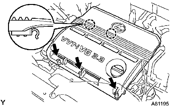
18. REMOVE V-BANK COVER SUB-ASSEMBLY
a. Using a 5 mm hexagon wrench, remove the 3 nuts.
b. Disconnect the 2 clips, and remove the cover.
19. REMOVE BATTERY
20. REMOVE AIR CLEANER CAP SUB-ASSEMBLY
21. REMOVE AIR CLEANER FILTER ELEMENT SUB-ASSEMBLY
22. REMOVE AIR CLEANER CASE
23. REMOVE V (COOLER COMPRESSOR TO CRANKSHAFT PULLEY) BELT NO.1
24. REMOVE VANE PUMP V BELT
25. REMOVE GENERATOR ASSEMBLY
26. REMOVE GENERATOR BRACKET NO.2
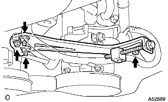
27. REMOVE GENERATOR BELT ADJUSTING BAR
a. Remove the 2 bolts, 2 nuts and adjusting bar.
28. REMOVE ENGINE MOVING CONTROL ROD
a. Remove the 4 bolts and control rod.
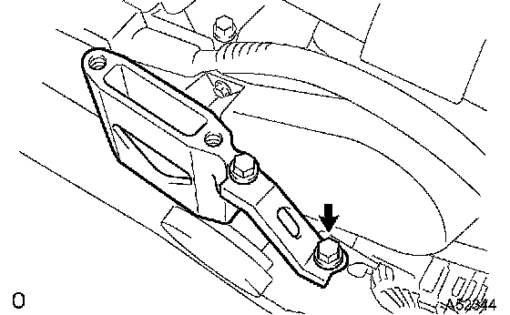
29. REMOVE ENGINE MOUNTING STAY NO.2 RH
a. Remove the bolt, mounting stay No. 2 RH and mounting bracket No. 2 RH.
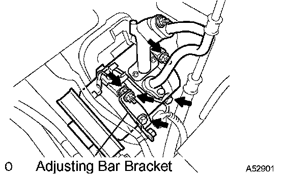
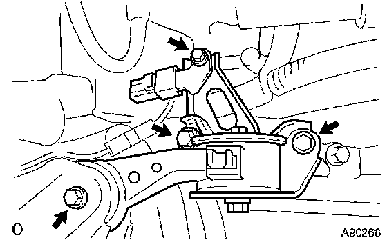
30. SEPARATE COMPRESSOR AND MAGNETIC CLUTCH
a. Remove the bolt, nut and adjusting bar bracket.
b. Remove the 3 bolts and disconnect the compressor.
HINT: Hang up the hoses instead of detaching them.
31. SEPARATE TRANSMISSION CONTROL CABLE ASSEMBLY
32. DISCONNECT UNION TO CHECK VALVE HOSE
a. Remove the vacuum hose for the brake booster.
33. DISCONNECT FUEL PIPE SUB-ASSEMBLY NO.1
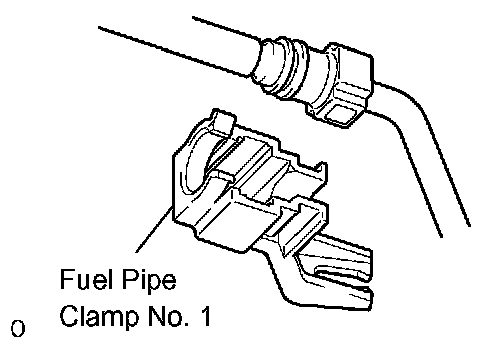
a. Remove the fuel pipe clamp.
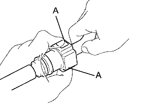
b. Disconnect the connector from the tube while pinching part A with fingers as shown in the illustration.
NOTICE:
^ Check for contamination in the pipe and around the connector. Clean if necessary and then disconnect the connector.
^ Disconnect the connector with your hands.
^ Do not bend, fold or rotate the nylon tube.
^ If the pipe and connector are stuck together, push and pull the connector until it comes free.
^ Put the pipe and connector ends in vinyl bags to prevent damage and contamination.
34. DISCONNECT HEATER INLET WATER HOSE
35. DISCONNECT HEATER OUTLET WATER HOSE
36. DISCONNECT RADIATOR HOSE INLET
37. DISCONNECT RADIATOR HOSE OUTLET
38. DISCONNECT OIL COOLER INLET TUBE NO.1
39. DISCONNECT OIL COOLER OUTLET TUBE NO.1
40. DISCONNECT OIL RESERVOIR TO PUMP HOSE NO.1