Inspection
INSPECTION1. HEADLAMP DIMMER SWITCH ASSEMBLY


a. Inspect light control switch continuity.
1. Measure the resistance according to the value(s) in the table.

b. Inspect headlight dimmer switch continuity.
1. Measure the resistance according to the value(s) in the table.
HINT: Turn light control switch to the HEAD position when checking "LOW BEAM" and "HI BEAM"

c. Inspect turn signal switch continuity.
1. Measure the resistance according to the value(s) in the table.

d. w/ Fog light:
Inspect front fog light switch continuity.
1. Measure the resistance according to the value(s) in the table.

2. BACK UP LAMP SWITCH ASSEMBLY
a. Measure the resistance according to the value(s) in the table.

3. STOP LAMP SWITCH ASSEMBLY (W/O CRUISE CONTROL)
a. Measure the resistance according to the value(s) in the table.


4. STOP LAMP SWITCH ASSEMBLY (W/ CRUISE CONTROL)
a. Measure the resistance according to the value(s) in the table.


5. HAZARD WARNING SIGNAL SWITCH ASSEMBLY
a. Measure the resistance according to the value(s) in the table.
b. Inspect illumination operation.
1. Connect the positive (+) lead from the battery to terminal 5 and the negative (-) lead to terminal 4, then check that the illumination comes on.

6. FRONT DOOR COURTESY LAMP SWITCH ASSEMBLY
a. Measure the resistance according to the value(s) in the table.

7. REAR DOOR COURTESY LAMP SWITCH ASSEMBLY
a. Measure the resistance according to the value(s) in the table.

8. LUGGAGE COMPARTMENT ROOM COURTESY LAMP SWITCH ASSEMBLY
a. Measure the resistance according to the value(s) in the table.
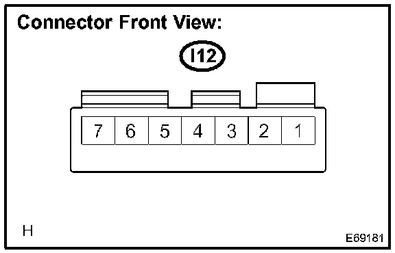
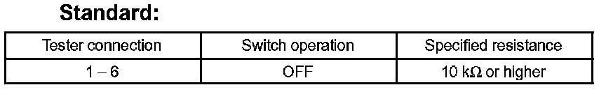
9. MAP LAMP ASSEMBLY (W/O SLIDING ROOF)
a. Measure the resistance according to the value(s) in the table.
b. Connect the positive (+) lead from the battery to terminal 1 and the negative (-) lead to terminal 6, then check that the illumination comes on when switch operation is ON position.

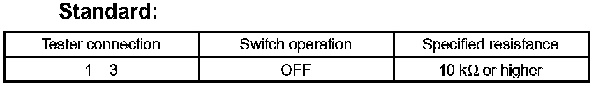
10. MAP LAMP ASSEMBLY (W/ SLIDING ROOF)
a. Measure the resistance according to the value(s) in the table.
b. Connect the positive (+) lead from the battery to terminal 1 and the negative (-) lead to terminal 3, then check that the illumination comes on when switch operation is ON position.

Standard:

11. ROOM LAMP ASSEMBLY
a. Measure the resistance according to the valve(s) in the table.
12. LUGGAGE COMPARTMENT LAMP ASSEMBLY NO.1
a. Connect the positive (+) lead from the battery to terminal 1 and the negative (-) lead to terminal 2, then check that the illumination comes on.


13. HEADLAMP RELAY
a. Measure the resistance according to the value(s) in the table.


14. FOG LAMP RELAY
a. Measure the resistance according to the value(s) in the table.


15. TAIL LAMP RELAY
a. Measure the resistance according to the value(s) in the table.


16. HEADLAMP DIMMER RELAY
a. Measure the resistance according to the value(s) in the table.

Standard:

17. LIGHT CONTROL RHEOSTAT
a. Connect the connector to the rheostat and inspect the wire harness side connector from the back side as shown in the table.
b. Inspect illumination operation.
1. Connect the positive (+) lead from the battery to terminal 2 and the negative (-) lead to terminal 3, then check that the illumination comes on.