Part 3
ENGINE UNITCOMPONENTS (Part 1):
COMPONENTS (Part 2):
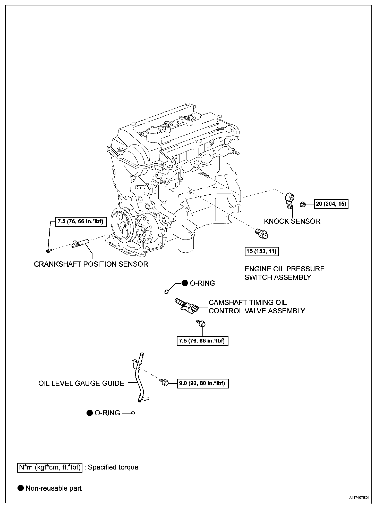
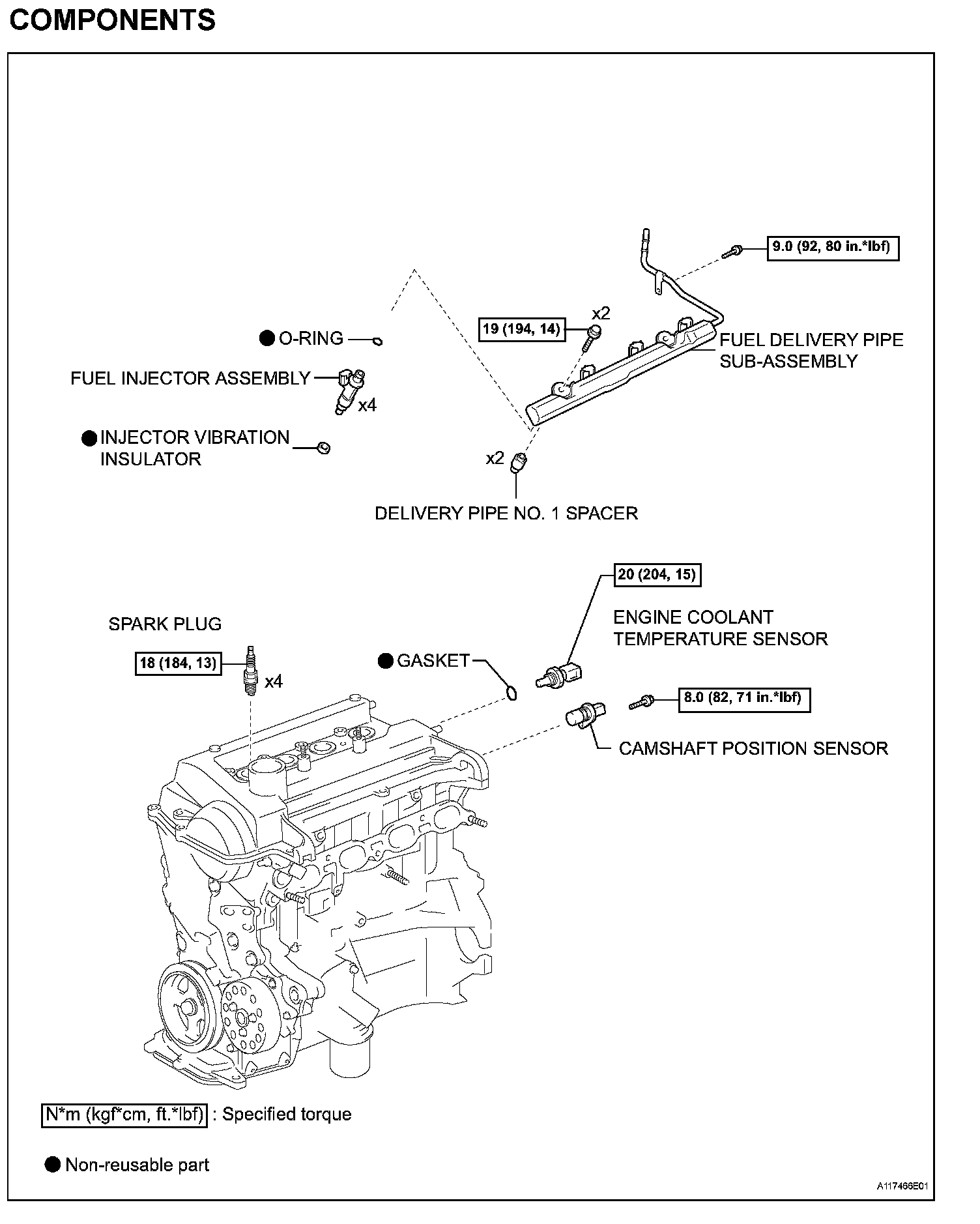
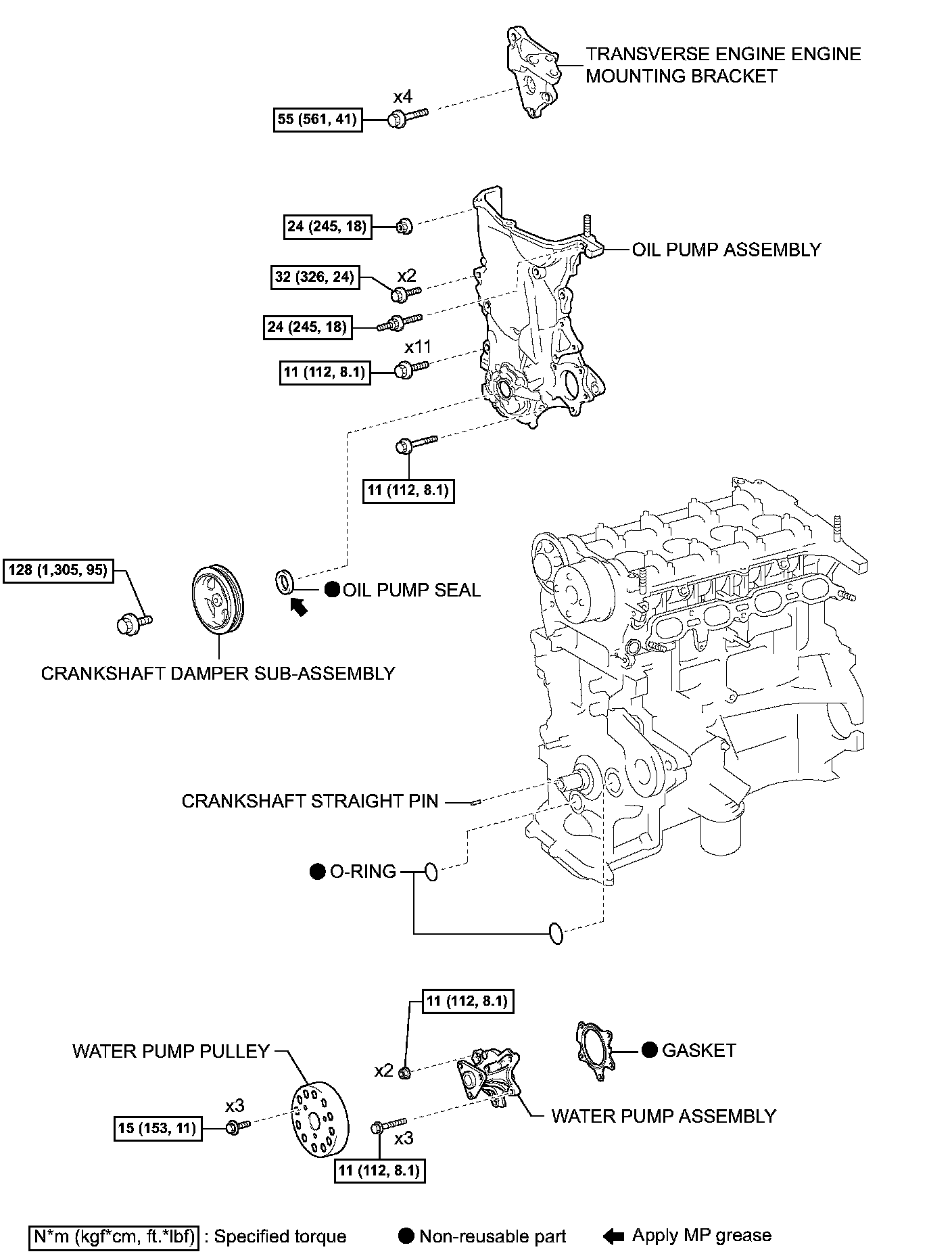
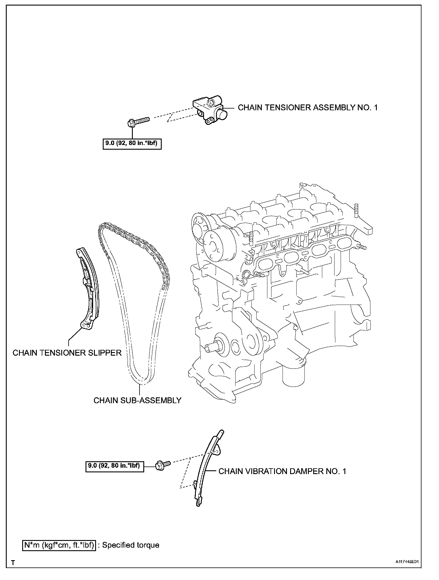
COMPONENTS (Part 3):
COMPONENTS (Part 4):
COMPONENTS (Part 5):
COMPONENTS (Part 6):
COMPONENTS (Part 7):

COMPONENTS (Part 8):
INSPECTION Continued

16. INSPECT RING GROOVE CLEARANCE
(a) Using a feeler gauge, measure the clearance between a new piston ring and the wall of the ring groove.
Ring groove clearance:
No. 1: 0.03 to 0.07 mm (0.0012 to 0.0028 in.)
No. 2: 0.02 to 0.06 mm (0.0008 to 0.0024 in.)

17. INSPECT PISTON RING END GAP
(a) Using a piston, push the piston ring, a little beyond the bottom of the ring travel, 110 mm (4.33 in.) from the top of the cylinder block.

(b) Using a feeler gauge, measure the end gap. Standard end gap:
No. 1: 0.25 to 0.35 mm (0.0098 to 0.0138 in.)
No. 2: 0.35 to 0.50 mm (0.0138 to 0.0197 in.)
Oil (Side Rail): 0.10 to 0.35 mm (0.0039 to 0.0138 in.)
Maximum end gap:
No. 1: 0.91 mm (0.0358 in.)
No. 2: 1.06 mm (0.0417 in.)
Oil (Side Rail): 0.82 mm (0.323 in.)

18. INSPECT CONNECTING ROD BOLT
(a) Using vernier calipers, measure the diameter of the bolt at the elongated portion.
Standard diameter: 6.6 to 6.7 mm (0.260 to 0.264 in.)
Minimum diameter: 6.4 mm (0.252 in.)
If the diameter is less than the minimum, replace the bolt.

19. INSPECT CRANKSHAFT
(a) Using a dial indicator and V-blocks, measure the circle runout as shown in the illustration.
Maximum circle runout: 0.03 mm (0.0012 in.)

(b) Using a micrometer, measure the diameter of each main journal.
Outside diameter: 45.988 to 46.000 mm (1.8106 to 1.8110 in.)
(c) Check each main journal for taper and out-of-roundness as shown.
Maximum taper and out-of-roundness: 0.02 mm (0.0008 in.)

(d) Using a micrometer, measure the diameter of each crank pin.
Outside diameter: 39.992 to 40.000 mm (1.5745 to 1.5748 in.)
(e) Check each crank pin for taper and out-of-roundness as shown.
Maximum taper and out-of-roundness: 0.02 mm (0.0008 in.)

(f) Wrap the chain around the timing sprocket.
(g) Using vernier calipers, measure the timing sprocket diameter with the chain.
Standard sprocket diameter (with chain): 51.72 mm (2.0362 in.)
Minimum sprocket diameter (with chain): 50.5 mm (1.988 in.)
NOTICE: Make sure that the vernier calipers are in contact with the chain rollers when measuring.

20. INSPECT CRANKSHAFT BEARING CAP SET BOLT
(a) Using vernier calipers, measure the tension portion diameter of the elongated portion.
Standard diameter: 7.3 to 7.5 mm (0.287 to 0.295 in.)
Minimum diameter: 7.2 mm (0.283 in.)
If the diameter is less than the minimum, replace the bolt.
21. INSPECT CRANKSHAFT OIL CLEARANCE
(a) Clean each main journal and bearing.
(b) Install the bearing onto the cylinder block and bearing cap.
(c) Place the crankshaft onto the cylinder block.

(d) Lay a strip of Plastigage across each journal.

(e) Examine the front marks and numbers and install the bearing cap onto the cylinder block.
(f) Apply a light coat of engine oil to the threads of the bearing cap bolts.

(g) Using SST, tighten the bolts in several steps to the specified torque in the sequence shown in the illustration. (*1)
SST 09011-38121
Torque: 22 N*m (224 kgf*cm, 16 ft.*lbf)

(h) Mark the front of the bearing cap bolts with paint.
(i) Retighten the bearing cap bolts by 90° in the same sequence as step (*1).
(j) Check that the painted mark is now at a 90° angle from the front.
NOTICE: Do not turn the crankshaft.
(k) Remove the bearing cap sub-assembly.

(l) Measure the Plastigage at its widest point.
Standard oil clearance: 0.01 to 0.023 mm (0.0004 to 0.0009 in.)
Maximum oil clearance: 0.07 mm (0.0028 in.)
NOTICE: Completely remove the Plastigage after the measurement.

(m) When replacing a standard bearing, replace it with one with the same number. If the number of the bearing cannot be found, select the correct bearing by adding together the numbers imprinted on the cylinder block and crankshaft, then select the bearing with the same number as the total. There are 4 sizes of standard bearings, marked 1, 2, 3 and 4 accordingly.
EXAMPLE: Cylinder Block 4 (A) + Crankshaft 3 (B) = Total 7 (Use Bearing 3)

