Pinout Values and Diagnostic Parameters
CAN COMMUNICATION SYSTEM:
TERMINALS OF ECU
1. JUNCTION CONNECTOR (NO. 1 CAN J/C, NO. 2 CAN J/C)
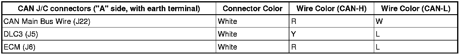
(a) No. 1 CAN J/C (For Coupe)
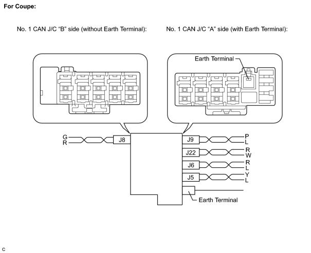
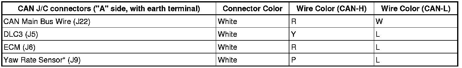

*: with VSC
(b) No. 1 CAN J/C (For Convertible)
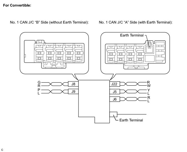

*: with VSC
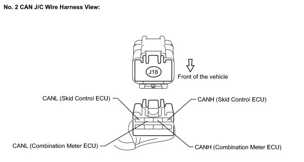
(c) No. 2 CAN J/C
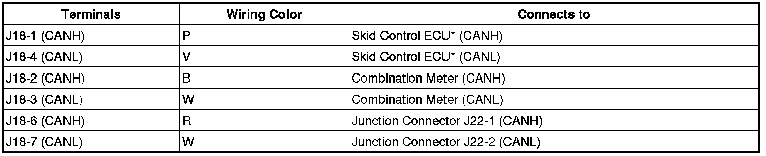
*: with VSC
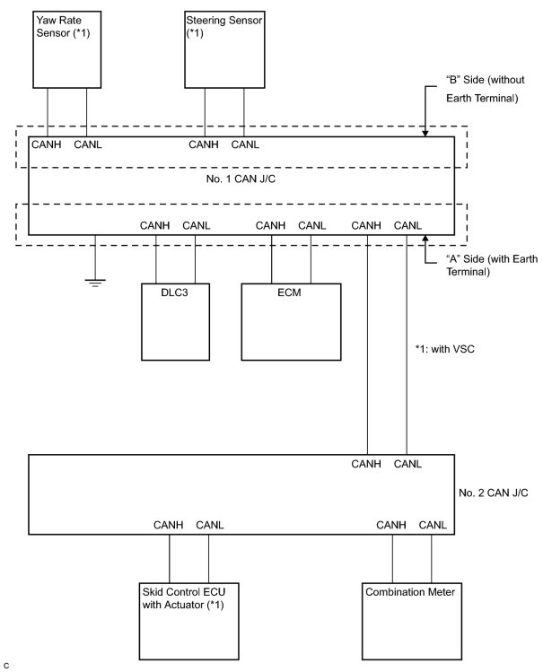
(d) The connection diagram of the components which are connected to the CAN J/C
2. DLC3
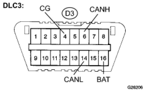
(a) Check DLC3.
(1) Turn the ignition switch off.
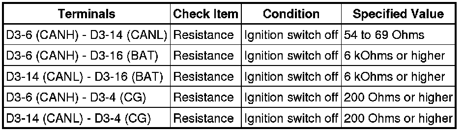
(2) Measure the resistance according to the value(s) in the table below.
Standard resistance:
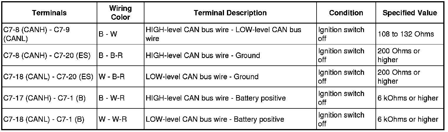
3. SKID CONTROL ECU
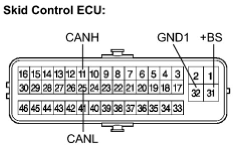
(a) Check the skid control ECU.
(1) Turn the ignition switch off.
(2) Disconnect the connector (S1) from the skid control ECU.
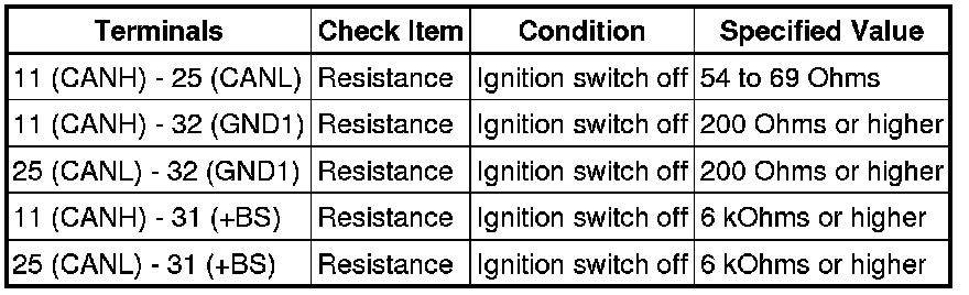
(3) Measure the resistance according to the value(s) in the table below.
Standard resistance:
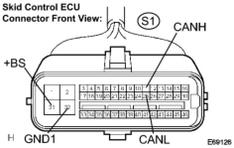
(b) Check the skid control ECU harness side connector (S1).
(1) Turn the ignition switch off.
(2) Disconnect the connector (S1) from the skid control ECU.
(3) Measure the resistance according to the value(s) in the table below.
Standard resistance:

4. STEERING SENSOR
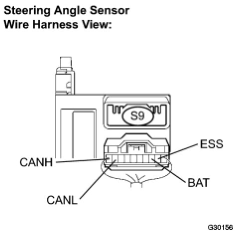
(a) Check the harness side connector (S9) of the steering sensor.
(1) Turn the ignition switch off.
(2) Disconnect the connector (S9) from the steering sensor.
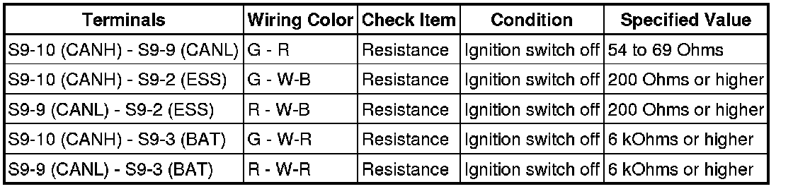
(3) Measure the resistance according to the value(s) in the table below.
Standard resistance:
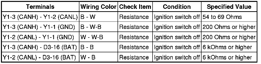
5. YAW RATE SENSOR
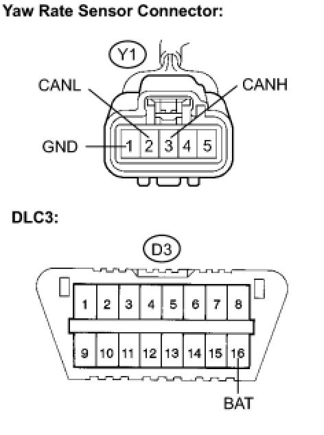
(a) Check the yaw rate sensor harness side connector (Y1).
(1) Turn the ignition switch off.
(2) Disconnect the connector (Y1) from the yaw rate sensor.
(3) Measure the resistance according to the value(s) in the table below.
Standard resistance:
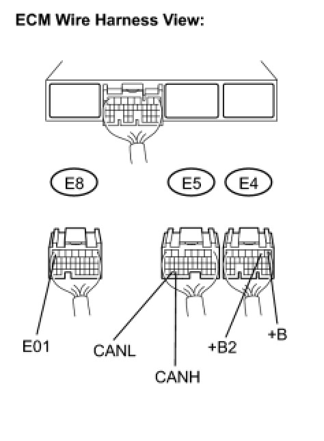
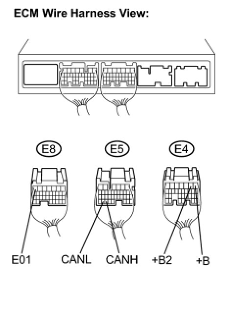
6. ECM
(a) 2AZ-FE
(1) Disconnect the connectors from the ECM.
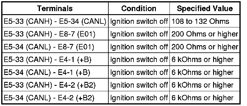
(2) Measure the resistance according to the value(s) in the table below.
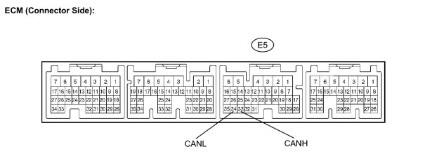
Standard resistance:

(3) Measure the resistance according to the value(s) in the table below.
Standard resistance:

(b) 3MZ-FE
(1) Disconnect the connectors from the ECM.
(2) Measure the resistance according to the value(s) in the table below.
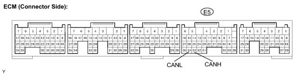
Standard resistance:

(3) Measure the resistance according to the value(s) in the table below.
Standard resistance:
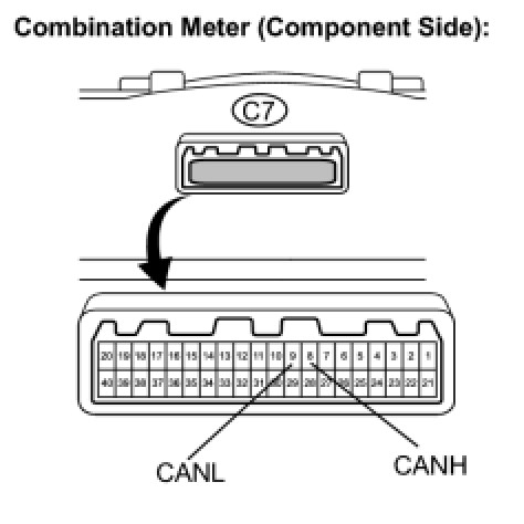
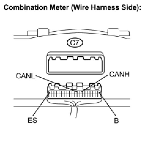
7. COMBINATION METER
(a) Disconnect the connector from the combination meter.
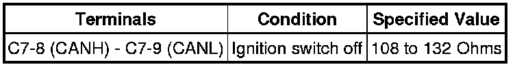
(b) Measure the resistance according to the value(s) in the table below.
Standard resistance:
(c) Measure the resistance according to the value(s) in the table below.
Standard resistance: