Engine Immobiliser System (w/ Smart Key System)
THEFT DETERRENT / KEYLESS ENTRY: ENGINE IMMOBILISER SYSTEM (w/ Smart Key System): B279A: Theft Deterrent System Communication Line High Fixation
B279A - Theft Deterrent System Communication Line High Fixation
DESCRIPTION
If the communication line (EFIO-IMI) to the ID code box is stuck on HI output, the ECM stores this DTC.

WIRING DIAGRAM

INSPECTION PROCEDURE
NOTICE:
- When the ID code box is replaced, refer to Registration Engine Immobiliser System (W/ Smart Key System).
- Inspect the fuses for circuits related to this system before performing the following inspection procedure.
PROCEDURE
1. CLEAR DTC
(a) Clear the DTCs Engine Immobiliser System (w/ Smart Key System).
NEXT -- Continue to next step.
2. CHECK FOR DTC
(a) Check for DTCs Engine Immobiliser System (w/ Smart Key System).
HINT
If DTCs other than DTC B279A are output, troubleshoot those DTCs first.
Result

C -- CHECK HARNESS AND CONNECTOR (ID CODE BOX - ECM)
B -- Go to DIAGNOSTIC TROUBLE CODE CHART Engine Immobiliser System (w/ Smart Key System)
A -- USE SIMULATION METHOD TO CHECK Electronic Circuit Inspection Procedure
3. CHECK HARNESS AND CONNECTOR (ID CODE BOX - ECM)
(a) Disconnect the F72 box connector.
(b) Disconnect the F50 ECM connector.
(c) Measure the resistance according to the value(s) in the table below.
Standard Resistance:

NG -- REPAIR OR REPLACE HARNESS OR CONNECTOR
OK -- Continue to next step.
4. CHECK ID CODE BOX (OUTPUT)
(a) Using an oscilloscope, check the waveform.

Text in Illustration

Measurement Condition

OK:
Waveform is output normally (refer to illustration).
NG -- CHECK HARNESS AND CONNECTOR (ID CODE BOX - BATTERY AND BODY GROUND)
OK -- REPLACE ECM Removal
5. CHECK HARNESS AND CONNECTOR (ID CODE BOX - BATTERY AND BODY GROUND)
(a) Disconnect the F72 box connector.
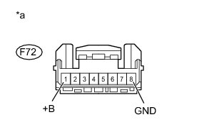
(b) Measure the voltage according to the value(s) in the table below.
Standard Voltage:

(c) Measure the resistance according to the value(s) in the table below.
Standard Resistance:

Text in Illustration

NG -- REPAIR OR REPLACE HARNESS OR CONNECTOR
OK -- Continue to next step.
6. REPLACE ID CODE BOX
(a) Replace the ID code box Removal.
NEXT -- Continue to next step.
7. REGISTER RECOGNITION CODES
(a) Register the recognition codes in the ECUs Engine Immobiliser System (W/ Smart Key System).
NEXT -- Continue to next step.
8. REGISTER ECU COMMUNICATION ID
(a) Register the ECU communication ID Engine Immobiliser System (W/ Smart Key System).
NEXT -- Continue to next step.
9. CLEAR DTC
(a) Clear the DTCs Engine Immobiliser System (w/ Smart Key System).
NEXT -- Continue to next step.
10. CHECK FOR DTC
(a) Check for DTCs Engine Immobiliser System (w/ Smart Key System).
OK:
DTC B279A is not output.
NG -- REPLACE ECM Removal
OK -- END (ID CODE BOX IS DEFECTIVE)