Mute Signal Circuit Between Stereo Component Tuner Assembly and Television Display Assembly
NAVIGATION: NAVIGATION SYSTEM: Mute Signal Circuit between Stereo Component Tuner Assembly and Television Display Assembly
- Mute Signal Circuit between Stereo Component Tuner Assembly and Television Display Assembly
DESCRIPTION
The navigation receiver assembly controls the volume according to the mute signal from the television display assembly.
The mute signal is sent to reduce noise and a popping sound generated when switching the mode etc. If there is an open in the circuit, noise can be heard from the speakers when changing the sound source. If there is a short in the circuit, even though the navigation receiver assembly is functioning normally, no sound or only an extremely faint sound can be heard.
WIRING DIAGRAM

INSPECTION PROCEDURE
PROCEDURE
1. INSPECT TELEVISION DISPLAY ASSEMBLY
(a) Measure the voltage according to the value(s) in the table below.
Standard Voltage:

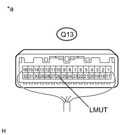
Text in Illustration
NG -- CHECK HARNESS AND CONNECTOR (STEREO COMPONENT TUNER- TELEVISION DISPLAY ASSEMBLY)
OK -- PROCEED TO NEXT SUSPECTED AREA SHOWN IN PROBLEM SYMPTOMS TABLE Symptom Related Diagnostic Procedures
2. CHECK HARNESS AND CONNECTOR (STEREO COMPONENT TUNER- TELEVISION DISPLAY ASSEMBLY)
(a) Disconnect the E28 stereo component tuner assembly connector.
(b) Disconnect the Q13 television display assembly connector.
(c) Measure the resistance according to the value(s) in the table below.
Standard Resistance:
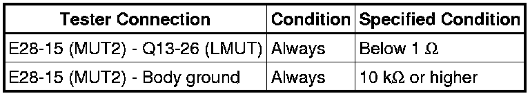
NG -- REPAIR OR REPLACE HARNESS OR CONNECTOR
OK -- Continue to next step.
3. REPLACE TELEVISION DISPLAY ASSEMBLY
(a) Replace the television display assembly and check if it operates normally Removal.
OK:
The navigation system operates normally.
NG -- PROCEED TO NEXT SUSPECTED AREA SHOWN IN PROBLEM SYMPTOMS TABLE Symptom Related Diagnostic Procedures
OK -- END