Removal
STEERING COLUMN: STEERING COLUMN ASSEMBLY: REMOVAL
1. TURN FRONT WHEELS TO FACE STRAIGHT AHEAD
2. REMOVE STEERING PAD
HINT
Refer to the instructions for Removal of the steering pad Removal.
3. REMOVE STEERING WHEEL ASSEMBLY Removal
4. REMOVE UPPER INSTRUMENT PANEL SUB-ASSEMBLY
HINT
Refer to the instructions for Removal of the upper instrument panel Removal.
5. REMOVE FRONT CONSOLE BOX ASSEMBLY
HINT
Refer to the instructions for Removal of the front console box Removal.
6. REMOVE FRONT NO. 1 CONSOLE BOX INSERT Removal
7. REMOVE FRONT NO. 2 CONSOLE BOX INSERT Removal
8. REMOVE LOWER CENTER INSTRUMENT PANEL FINISH PANEL (for Manual Transaxle) Removal
9. REMOVE LOWER CENTER INSTRUMENT PANEL FINISH PANEL (for Automatic Transaxle) Removal
10. REMOVE NO. 1 SWITCH HOLE BASE Removal
11. REMOVE LOWER INSTRUMENT PANEL FINISH PANEL SUB-ASSEMBLY Removal
12. REMOVE LOWER STEERING COLUMN COVER
NOTICE:
Removing the lower steering column cover in the incorrect order will cause the lower steering column cover to break.
(a) Push the right and left sides of the lower steering column cover, and disengage the 4 claws.
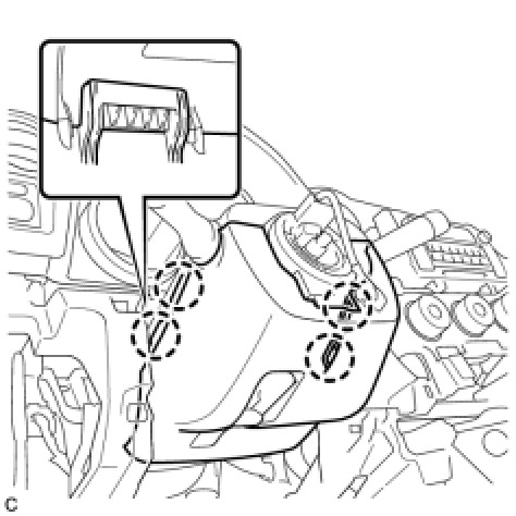
(b) Insert fingers into the opening of the tilt lever of the lower steering column cover to disengage the claw.

HINT
Spread the claw to disengage it.
(c) Using a screwdriver, insert the tip into each service hole to disengage the 2 claws and remove the lower steering column cover as shown in the illustration.

13. REMOVE UPPER STEERING COLUMN COVER
(a) Disengage the claw and the 2 pins, and remove the upper steering column cover.

14. REMOVE TURN SIGNAL SWITCH ASSEMBLY WITH SPIRAL CABLE SUB-ASSEMBLY
(a) Disconnect the connectors from the turn signal switch assembly with the spiral cable sub-assembly.
(b) Use pliers to hold the clamp and raise the claw with a screwdriver. Remove the turn signal switch assembly with the spiral cable sub-assembly from the steering column assembly.

15. REMOVE COLUMN HOLE COVER SILENCER SHEET
(a) Turn back the floor carpet, and remove the 2 clips and column hole cover silencer sheet.

16. SEPARATE NO. 2 STEERING INTERMEDIATE SHAFT ASSEMBLY (for 2WD)
(a) Put matchmarks on the No. 2 steering intermediate shaft assembly and the steering intermediate shaft.

(b) Remove the bolt and separate the No. 2 steering intermediate shaft assembly from the steering intermediate shaft.
17. SEPARATE NO. 2 STEERING INTERMEDIATE SHAFT ASSEMBLY (for 4WD)
(a) Put matchmarks on the No. 2 steering intermediate shaft assembly and the power steering link assembly.
(b) Remove the bolt and separate the No. 2 steering intermediate shaft assembly from the power steering link assembly.
18. REMOVE INSTRUMENT PANEL SUB REINFORCEMENT
(a) Remove the 2 bolts and instrument panel sub reinforcement.

19. REMOVE NO. 2 AIR DUCT SUB-ASSEMBLY
(a) Disengage the 2 claws and remove the No. 2 air duct sub-assembly.

20. REMOVE TRANSPONDER KEY AMPLIFIER (w/ Engine Immobiliser System)
(a) Slide the transponder key amplifier to disengage the 2 claws as shown in the illustration.

(b) Disconnect the connector and remove the transponder key amplifier.

21. REMOVE STOP LIGHT SWITCH ASSEMBLY Removal
22. REMOVE STEERING POST ASSEMBLY
(a) Disconnect the connector from the power steering ECU assembly.

HINT
Pull out the lock of the lock lever, disengage the claw, and raise the lock lever to disconnect the connector, as shown in the illustration.
(b) Disconnect the connector from the power steering ECU assembly.

(c) Separate the wire harness clamp from the power steering ECU assembly.

(d) Remove the bolt, 2 nuts, and steering post assembly.

NOTICE:
* Do not release the tilt lever when the steering column assembly is not installed on the vehicle.
* Do not drop or strike the steering column assembly. If dropped or struck, replace it with a new one.
23. REMOVE NO. 2 STEERING INTERMEDIATE SHAFT ASSEMBLY
(a) Put matchmarks on the No. 2 steering intermediate shaft assembly and the steering column assembly.

(b) Remove the bolt and the No. 2 steering intermediate shaft assembly from the steering column assembly.
