Radio Broadcast cannot be Received (Bad Reception)
AUDIO / VIDEO: AUDIO AND VISUAL SYSTEM: Radio Broadcast cannot be Received (Bad Reception)
- Radio Broadcast cannot be Received (Bad Reception)
WIRING DIAGRAM

INSPECTION PROCEDURE
PROCEDURE
1. CHECK RADIO RECEIVER ASSEMBLY
(a) Check the radio automatic station search function.
(1) Check the radio automatic station search function by activating it.
OK:
The radio automatic station search function works properly.
NG -- CHECK OPTIONAL COMPONENTS
OK -- REPLACE RADIO RECEIVER ASSEMBLY Removal
2. CHECK OPTIONAL COMPONENTS
(a) Check for optional components (sunshade film, telephone antenna, etc.).
(1) Check if any optional components that may decrease reception capacity, such as sunshade film or a telephone antenna, are installed.
OK:
Optional components are installed.
NOTICE:
Do not remove any optional components installed by the customer without his or her consent.
NG -- CHECK RADIO RECEIVER ASSEMBLY
OK -- REMOVE OPTIONAL COMPONENTS AND CHECK AGAIN (SEE NOTICE ABOVE)
3. CHECK RADIO RECEIVER ASSEMBLY
(a) Remove the antenna plug from the radio receiver assembly.
(b) Turn the ignition switch to ACC with the radio receiver assembly connector connected.
(c) Turn the radio on and tune into AM mode.
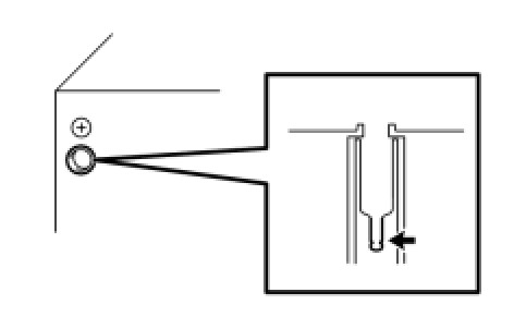
(d) Place a screwdriver, thin wire or other metal object on the radio receiver antenna jack and check that noise can be heard from the speaker.
OK:
Noise occurs.
NG -- REPLACE RADIO RECEIVER ASSEMBLY Removal
OK -- Continue to next step.
4. CHECK HARNESS AND CONNECTOR (RADIO RECEIVER - AMPLIFIER ANTENNA)
(a) for 8 Speakers:
(1) Disconnect the I1 radio receiver assembly connector.

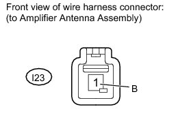
(2) Disconnect the I23 amplifier antenna assembly connector.
(3) Measure the resistance according to the value(s) in the table below.
Standard Resistance:

(b) for 14 Speakers:
(1) Disconnect the I4 radio receiver assembly connector.

(2) Disconnect the I23 amplifier antenna assembly connector.
(3) Measure the resistance according to the value(s) in the table below.
Standard Resistance:

NG -- REPAIR OR REPLACE HARNESS OR CONNECTOR
OK -- Continue to next step.
5. CHECK RADIO RECEIVER ASSEMBLY
(a) Disconnect the radio receiver assembly connector.
(b) Measure the voltage according to the value(s) in the table below.
Standard Voltage:

NG -- REPLACE RADIO RECEIVER ASSEMBLY Removal
OK -- Continue to next step.
6. CHECK ANTENNA CORD SUB-ASSEMBLY
(a) Remove the antenna plug of the radio receiver and antenna.
(b) Measure the resistance between the antenna and radio receiver to check for an open circuit in the antenna cord.
Standard Resistance:
Below 1 Ohms
(c) Measure the resistance between the antenna cord and body ground to check for a short circuit in the antenna cord.
Standard Resistance:
10 kOhms or higher
NG -- REPLACE ANTENNA CORD SUB-ASSEMBLY
OK -- Continue to next step.
7. REPLACE AMPLIFIER ANTENNA ASSEMBLY
(a) Replace the amplifier antenna assembly and check if radio broadcasts can be received normally.
OK:
Radio broadcasts can be received.
NG -- REPLACE RADIO RECEIVER ASSEMBLY Removal
OK -- NORMAL OPERATION