No Answer-Back
DOOR LOCK: WIRELESS DOOR LOCK CONTROL SYSTEM: No Answer-Back
- No Answer-Back
DESCRIPTION
In some cases, wireless door lock control functions are normal but the hazard warning light and/or wireless door lock buzzer answer-back function(s) does not operate. In such cases, the hazard warning light and wireless door lock buzzer signals output from the main body ECU (multiplex network body ECU) may be malfunctioning.
WIRING DIAGRAM
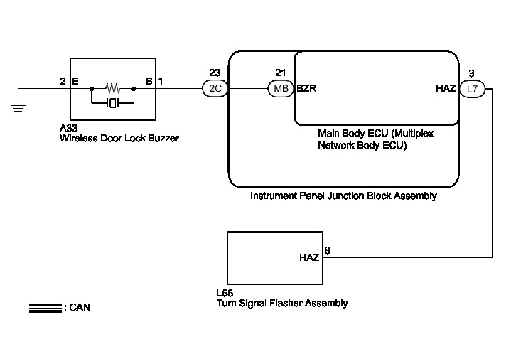
INSPECTION PROCEDURE
PROCEDURE
1. READ VALUE USING TECHSTREAM (ANSWER-BACK OPERATION)
(a) Connect the Techstream to the DLC3.
(b) Turn the power switch on (IG).
(c) Turn the Techstream on.
(d) Enter the following menus: Body Electrical / Main Body / Utility / Customize.
(e) Select the setting by referring to the table below.
Wireless Door Lock Control System
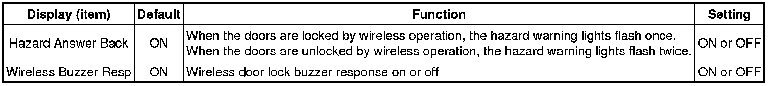
Result:
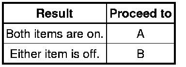
B -- PERFORM CUSTOMIZE FUNCTION (ANSWER-BACK FUNCTION) Programming and Relearning
A -- Continue to next step.
2. CHECK WIRELESS DOOR LOCK CONTROL FUNCTIONS
(a) Check the wireless door lock control function by the electrical key transmitter sub-assembly.
Result:
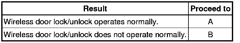
B -- GO TO SMART KEY SYSTEM How To Proceed With Troubleshooting
A -- Continue to next step.
3. READ VALUE USING TECHSTREAM (DOOR LOCK POSITION SWITCH)
(a) Connect the Techstream to the DLC3.
(b) Turn the power switch on (IG).
(c) Turn the Techstream on.
(d) Enter the following menus: Body Electrical / Main Body / Data List.
(e) Read the Data List according to the display on the Techstream.
Main Body (Main Body ECU (Multiplex Network Body ECU))
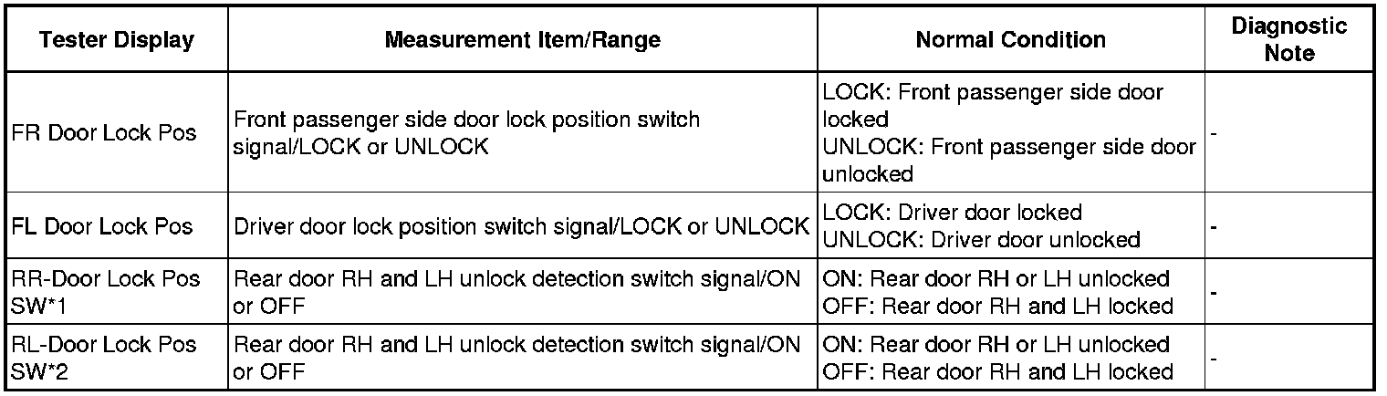
* *1: When checking RR- Door Lock Pos SW, make sure to check it with the rear door LH locked.
* *2: When checking RL- Door Lock Pos SW, make sure to check it with the rear door RH locked.
OK:
The Techstream should display as shown in the table according to door lock operation.
Result:
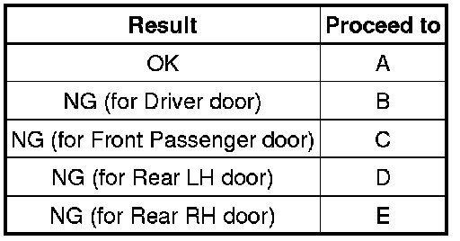
B -- GO TO LIGHTING SYSTEM (Proceed to Door Unlock Detection Switch Circuit) Door Unlock Detection Switch Circuit
C -- GO TO LIGHTING SYSTEM (Proceed to Door Unlock Detection Switch Circuit) Door Unlock Detection Switch Circuit
D -- GO TO LIGHTING SYSTEM (Proceed to Door Unlock Detection Switch Circuit) Door Unlock Detection Switch Circuit
E -- GO TO LIGHTING SYSTEM (Proceed to Door Unlock Detection Switch Circuit) Door Unlock Detection Switch Circuit
A -- Continue to next step.
4. CHECK WIRELESS ANSWER-BACK OPERATION
(a) Check the wireless answer-back operation by wireless door lock control function.
Result:
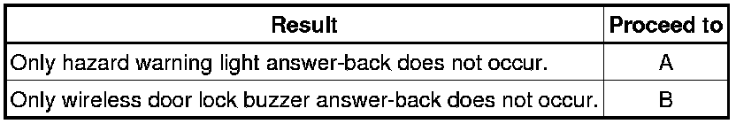
B -- PERFORM ACTIVE TEST USING TECHSTREAM (WIRELESS DOOR LOCK BUZZER)
A -- Continue to next step.
5. CHECK HAZARD WARNING LIGHT OPERATION
(a) Check that the hazard warning lights flash continuously when the hazard warning signal switch is pressed.
OK:
Hazard warning lights flash continuously.
NG -- GO TO LIGHTING SYSTEM How To Proceed With Troubleshooting
OK -- Continue to next step.
6. PERFORM ACTIVE TEST USING TECHSTREAM
(a) Connect the Techstream to the DLC3.
(b) Turn the power switch on (IG).
(c) Turn the Techstream on.
(d) Enter the following menus: Body Electrical / Main Body / Active Test.
(e) Perform the Active Test according to the display on the Techstream.
Main Body (Main Body ECU (Multiplex Network Body ECU))

Result:
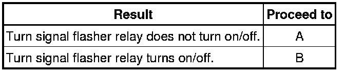
B -- REPLACE MAIN BODY ECU (MULTIPLEX NETWORK BODY ECU) Removal
A -- Continue to next step.
7. CHECK HARNESS AND CONNECTOR (TURN SIGNAL FLASHER ASSEMBLY - MAIN BODY ECU)
(a) Disconnect the L55 turn signal flasher assembly and L7 main body ECU (multiplex network body ECU) connectors.
(b) Measure the resistance according to the value(s) in the table below.
Standard Resistance:

NG -- REPAIR OR REPLACE HARNESS OR CONNECTOR
OK -- REPLACE MAIN BODY ECU (MULTIPLEX NETWORK BODY ECU) Removal
8. PERFORM ACTIVE TEST USING TECHSTREAM (WIRELESS DOOR LOCK BUZZER)
(a) Connect the Techstream to the DLC3.
(b) Turn the power switch on (IG).
(c) Turn the Techstream on.
(d) Enter the following menus: Body Electrical / Main Body / Active Test.
(e) Perform the Active Test according to the display on the Techstream.
Main Body (Main Body ECU (Multiplex Network Body ECU))

Result:

B -- REPLACE MAIN BODY ECU (MULTIPLEX NETWORK BODY ECU) Removal
A -- Continue to next step.
9. CHECK HARNESS AND CONNECTOR (WIRELESS DOOR LOCK BUZZER - INSTRUMENT PANEL JUNCTION BLOCK ASSEMBLY)
(a) Disconnect the A33 wireless door lock buzzer and 2C instrument panel junction block assembly connectors.
(b) Measure the resistance according to the value(s) in the table below.
Standard Resistance:
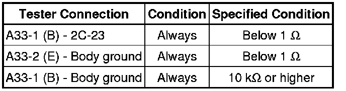
NG -- REPAIR OR REPLACE HARNESS OR CONNECTOR
OK -- Continue to next step.
10. CHECK INSTRUMENT PANEL JUNCTION BLOCK ASSEMBLY
(a) Remove the instrument panel junction block assembly Removal.
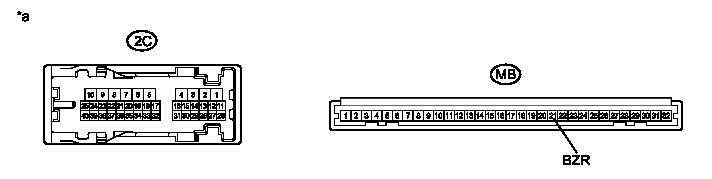
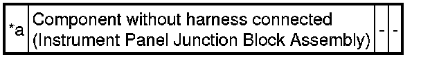
Text in Illustration
(b) Measure the resistance according to the value(s) in the table below.
Standard Resistance:
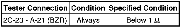
NG -- REPLACE INSTRUMENT PANEL JUNCTION BLOCK ASSEMBLY Removal
OK -- Continue to next step.
11. REPLACE WIRELESS DOOR LOCK BUZZER
(a) Temporarily replace the wireless door lock buzzer with a new one Removal.
NEXT -- Continue to next step.
12. CHECK WIRELESS DOOR LOCK BUZZER OPERATION
(a) Check the operation of the wireless answer-back function.
OK:
Wireless answer-back function operates normally.
NG -- REPLACE MAIN BODY ECU (MULTIPLEX NETWORK BODY ECU) Removal
OK -- END (WIRELESS DOOR LOCK BUZZER WAS DEFECTIVE)