Only Wireless Control Function Is Inoperative
DOOR LOCK: WIRELESS DOOR LOCK CONTROL SYSTEM: Only Wireless Control Function is Inoperative
- Only Wireless Control Function is Inoperative
DESCRIPTION
When the wireless operation of the door lock functions do not operate, a malfunction or wave interference may be occurring in either of the following: 1) the signal communication line between the door control receiver and certification ECU (smart key ECU assembly) (the line used for wireless operations): or 2) the electrical key transmitter sub-assembly. If the wireless lock operations cannot be performed, there may be key malfunctions, wave interference or problems in the communication which is used for the wireless function between the door control receiver and certification ECU (smart key ECU assembly).
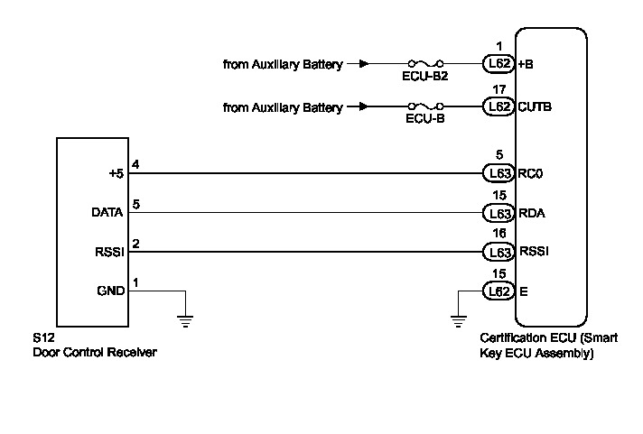
WIRING DIAGRAM
INSPECTION PROCEDURE
NOTICE:
* Check that there are no electrical key transmitter sub-assemblies in the vehicle.
* Before performing the inspection, check that DTC B1242 (wireless door lock control) is not output Wireless Door Lock Control System.
* Inspect the fuses for circuits related to this system before performing the following inspection procedure.
* When replacing the certification ECU (smart key ECU assembly) or electrical key transmitter sub-assembly, refer to the Service Bulletin.
* Troubleshooting should be started after confirming that the customize status of the wireless control function has been switched on Programming and Relearning.
* Door control receiver has a constant voltage (5 V) supply circuit connected to terminal "+5".
PROCEDURE
1. SYSTEM CHECK
(a) Check the vehicle specification.
Result:
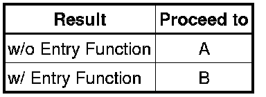
B -- GO TO PROBLEM SYMPTOMS TABLE Problem Symptoms Table
A -- Continue to next step.
2. INSPECT AUXILIARY BATTERY VOLTAGE
(a) Measure the voltage of the auxiliary battery with the power switch off.
Standard voltage:
11 to 14 V
HINT
It may be possible to tell whether the auxiliary battery is depleted by operating the horn.
If the voltage is below 11 V, recharge or replace the auxiliary battery before proceeding.
NEXT -- Continue to next step.
3. CHECK FOR DTC
(a) Open the driver door using the mechanical key built into the electrical key transmitter sub-assembly.
(b) Connect the Techstream and check for DTCs Reading and Clearing Diagnostic Trouble Codes.
HINT
When using the Techstream with the power switch off to troubleshoot: Connect the Techstream to the DLC3 and turn a courtesy light switch on and off at 1.5-second intervals until communication between the Techstream and vehicle begins.
OK:
DTC is not output.
NG -- GO TO DIAGNOSTIC TROUBLE CODE CHART Wireless Door Lock Control System
OK -- Continue to next step.
4. CHECK POWER DOOR LOCK CONTROL SYSTEM
(a) When the door control switch on the multiplex network master switch assembly on the driver door is operated, check that the doors unlock and lock according to the switch operation Operation Check.
OK:
Door locks operate normally.
NG -- GO TO POWER DOOR LOCK CONTROL SYSTEM How To Proceed With Troubleshooting
OK -- Continue to next step.
5. CHECK ELECTRICAL KEY TRANSMITTER SUB-ASSEMBLY
(a) When a known good registered electrical key transmitter sub-assembly is used, check that the wireless functions operate normally.
Result

B -- CHECK WAVE ENVIRONMENT
A -- Continue to next step.
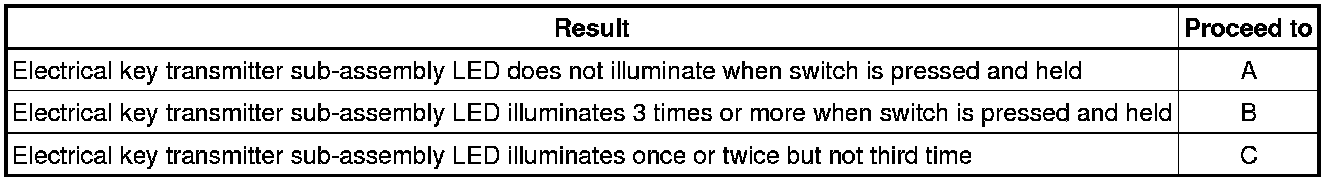
6. CHECK ELECTRICAL KEY TRANSMITTER SUB-ASSEMBLY (LED)
(a) Press and hold the lock switch of the electrical key transmitter sub-assembly for 5 seconds and check the number of times that the electrical key transmitter sub-assembly LED illuminates.
Result
HINT
* The key sends voltage information to the certification ECU (smart key ECU assembly) when it is being used. The certification ECU (smart key ECU assembly) displays "Yes" for the "Key Low Battery" item of the Data List when this voltage information indicates 2.1 V or less Smart Key System (for Entry Function).
* Even if the transmitter battery is depleted, it is still possible to start the hybrid control system by holding the key against the power switch, depressing the brake pedal and pressing the power switch.
B -- REPLACE ELECTRICAL KEY TRANSMITTER SUB-ASSEMBLY
C -- REPLACE TRANSMITTER BATTERY Transmitter Battery
A -- Continue to next step.
7. INSPECT TRANSMITTER BATTERY (VOLTAGE)
(a) Inspect the transmitter battery
(1) Remove the transmitter battery from the electrical key transmitter sub-assembly that does not operate Removal.

(2) Attach a lead wire (0.60 mm [0.0236 in.] in diameter or less including wire sheath) with tape or equivalent to the negative terminal.
NOTICE:
Do not wrap the lead wire around a terminal, wedge it between terminals, or solder it. The terminal may be deformed or damaged, and the transmitter battery will not be able to be installed correctly.
(3) Carefully pull the lead wire out from the position shown in the illustration and install the previously removed transmitter battery.
(4) Measure the voltage of the transmitter battery.
NOTICE:
When replacing the transmitter battery, before starting work, remove static electricity that has built up in the body by touching, for example, the vehicle to prevent the electrical key transmitter sub-assembly from being damaged.
HINT
* Measure the transmitter battery voltage while pressing the LOCK or UNLOCK switch on the electrical key transmitter sub-assembly.
* Perform the measurement when the key is at room temperature.
* The key sends voltage information to the certification ECU (smart key ECU assembly) when it is transmitting. When this voltage is 2.1 V or less the Data List item "Key Low Battery" displays "Yes" Smart Key System (for Entry Function).

Standard Voltage:
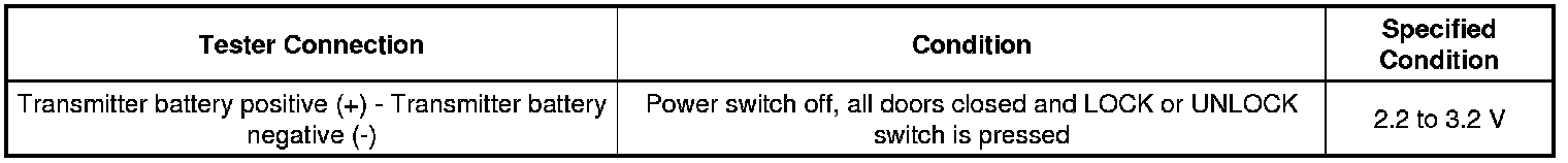
NG -- REPLACE TRANSMITTER BATTERY Transmitter Battery
OK -- REPLACE ELECTRICAL KEY TRANSMITTER SUB-ASSEMBLY
8. CHECK WAVE ENVIRONMENT
(a) Bring the electrical key transmitter sub-assembly near the door control receiver and perform a wireless function operation check.
HINT
* When the electrical key transmitter sub-assembly is brought near the door control receiver, the possibility of electric wave interference decreases, and it can be determined if electric wave interference is causing the problem symptom.
* If the inspection result is that the problem only occurs in certain locations or at certain times of day, the possibility of wave interference is high. Also, added vehicle components may cause wave interference. If installed, remove them and perform the operation check.
* There may be electric wave interference if the vehicle is near broadcasting antennas, large video displays, wireless garage door opener systems, wireless security cameras, home security systems, etc. In this case, move the vehicle to a different location and check if there is any improvement.
OK:
Wireless functions operate normally.
NG -- CHECK POWER SOURCE
OK -- AFFECTED BY WAVE INTERFERENCE
9. CHECK POWER SOURCE
(a) When the power switch is off, check that the functions other than the wireless functions recognize the power source mode as being off.
HINT
* Check if systems that should not be operating when the power source mode is off are operating.
* When the certification ECU (smart key ECU assembly) mistakenly determines the power source mode to be on (IG) for some reason (example: an ECU mistakenly determines the power source mode to be on (IG) and sends that information to the certification ECU (smart key ECU assembly)) even though the power source mode is off, the certification ECU (smart key ECU assembly) stops the wireless functions.
OK:
When the power source mode is off, functions other than the wireless functions recognize the power source mode as being off.
NG -- GO TO PUSH-BUTTON START SYSTEM How To Proceed With Troubleshooting
OK -- Continue to next step.
10. CHECK HARNESS AND CONNECTOR (CERTIFICATION ECU - AUXILIARY BATTERY AND BODY GROUND)
(a) Disconnect the L62 ECU connector.
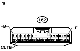
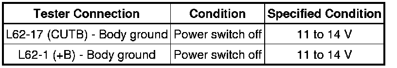
(b) Measure the voltage according to the value(s) in the table below.
Standard Voltage:
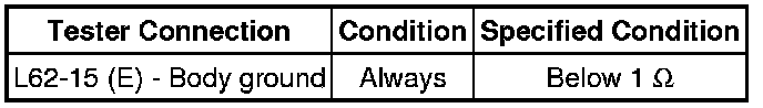
(c) Measure the resistance according to the value(s) in the table below.
Standard Resistance:
Text in Illustration
NG -- REPAIR OR REPLACE HARNESS OR CONNECTOR
OK -- Continue to next step.
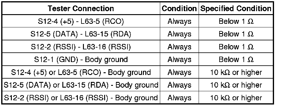
11. CHECK HARNESS AND CONNECTOR (DOOR CONTROL RECEIVER - CERTIFICATION ECU AND BODY GROUND)
(a) Disconnect the S12 door control receiver connector.
(b) Disconnect the L63 certification ECU (smart key ECU assembly) connector.
(c) Measure the resistance according to the value(s) in the table below.
Standard Resistance:
NG -- REPAIR OR REPLACE HARNESS OR CONNECTOR
OK -- Continue to next step.
12. CHECK DOOR CONTROL RECEIVER (OPERATION)
(a) Temporarily replace the door control receiver with a new or normally functioning one Removal.
(b) Check that the wireless functions operate normally.
OK:
Wireless functions operate normally.
NG -- REPLACE CERTIFICATION ECU (SMART KEY ECU ASSEMBLY)
OK -- END (DOOR CONTROL RECEIVER WAS DEFECTIVE)