Part 1
2ZR-FXE ENGINE CONTROL: SFI SYSTEM: EVAP System
- EVAP System
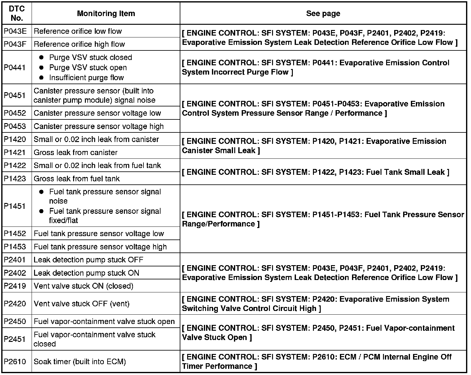
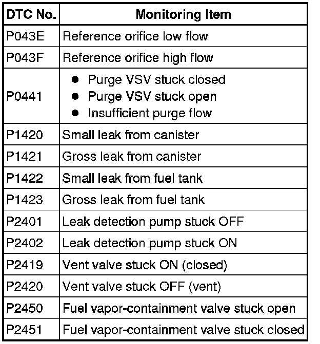
RELATED DTCS
DESCRIPTION
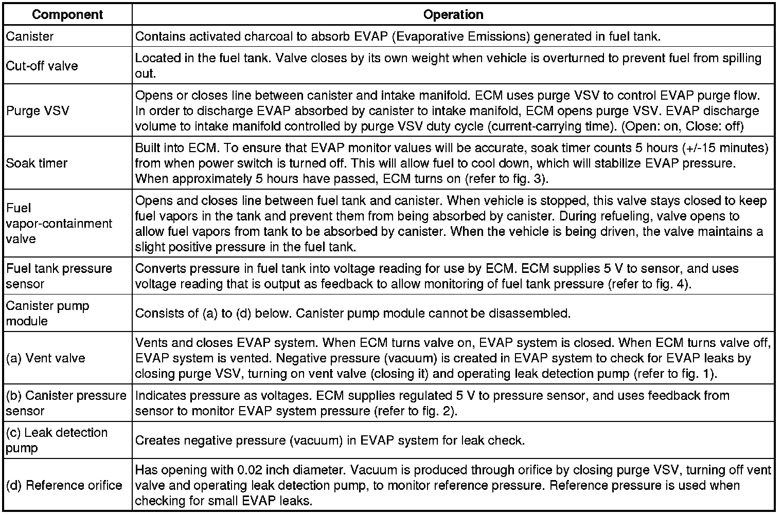
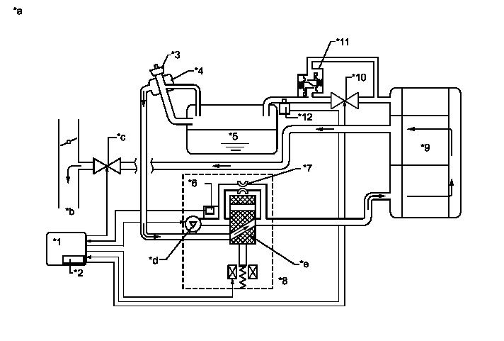
While the engine is running, if predetermined conditions (closed loop, etc.) are met, the purge VSV is opened by the ECM and stored fuel vapors in the canister are purged to the intake manifold. The ECM will change the duty cycle ratio of the purge VSV to control purge flow volume.
Purge flow volume is also determined by the intake manifold pressure. Atmospheric pressure is allowed to enter the canister through the vent valve to ensure that purge flow is maintained when negative pressure (vacuum) is applied to the canister.
The ECM monitors the condition of both the key-off monitor and purge flow monitor to ensure proper operation of the EVAP system.
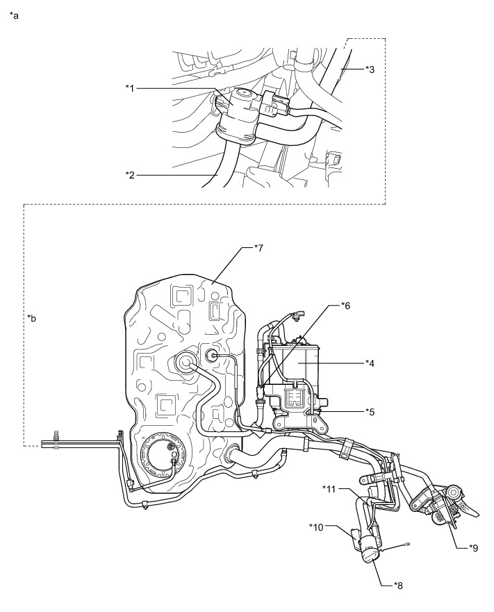
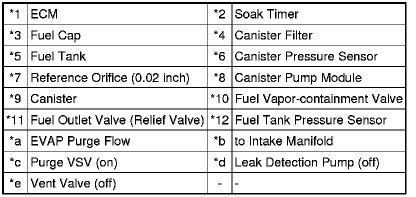
Text in Illustration
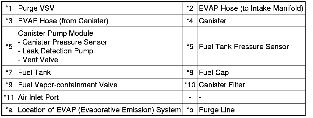
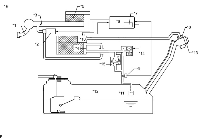
Text in Illustration
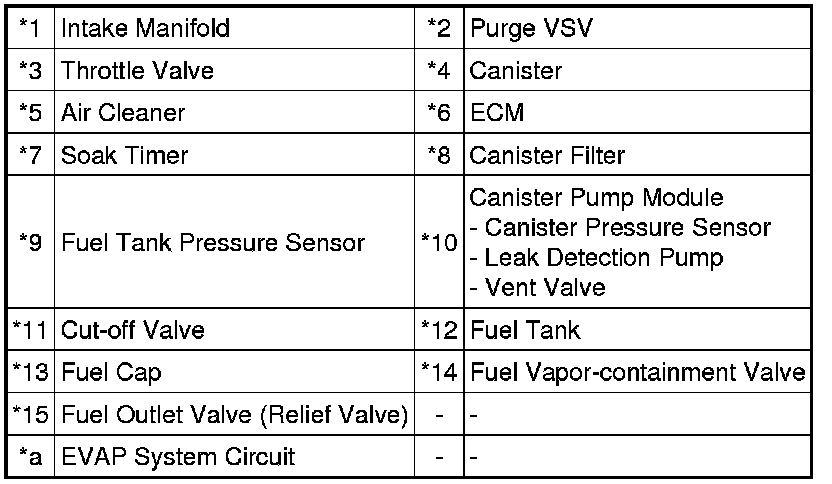

Text in Illustration
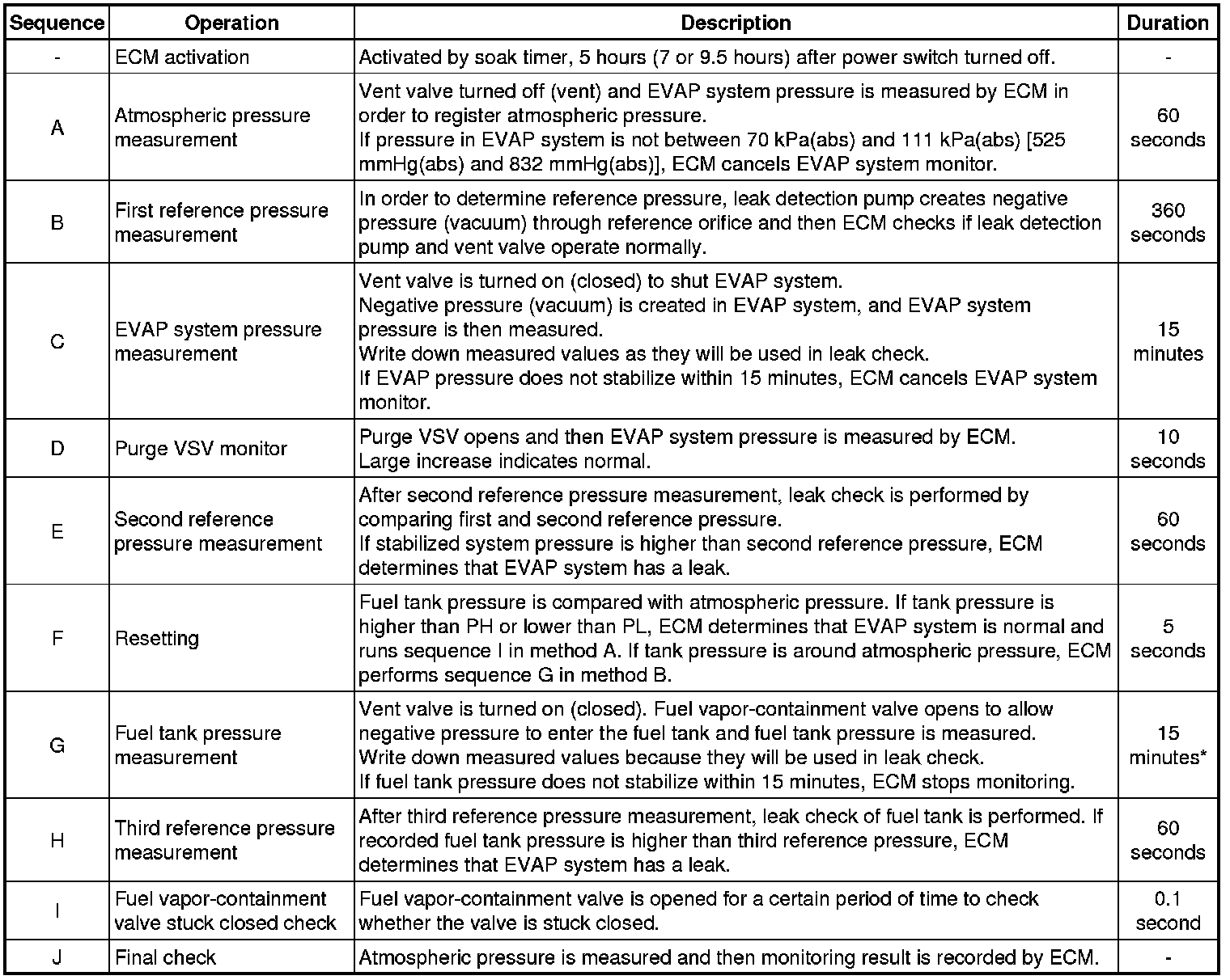
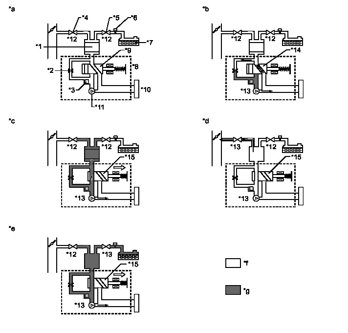
Key-off Monitor
This monitor checks for EVAP (evaporative emission) system leaks and canister pump module malfunctions. The monitor starts 5 hours* after the power switch is turned off. At least 5 hours are required for the fuel to cool down to stabilize the EVAP pressure, thus making the EVAP system monitor more accurate.
The leak detection pump creates negative pressure (vacuum) in the EVAP system and the pressure is measured. Finally, the ECM monitors for leaks from the EVAP system, and malfunctions in both the canister pump module and purge VSV based on the EVAP pressure.
HINT
*: If the engine coolant temperature is not less than 35°C (95°F) 5 hours after the power switch is turned off, the monitor check starts 2 hours later. If it is still not less than 35°C (95°F) 7 hours after the power switch is turned off, the monitor check starts 2.5 hours later.
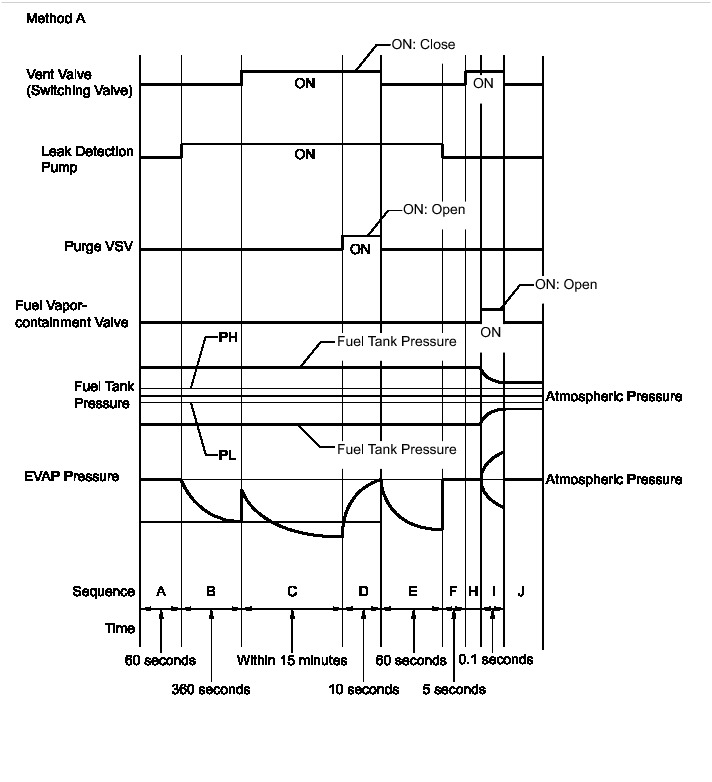
* If the fuel tank pressure is higher or lower than the atmospheric pressure, the system determines that there are no leaks in the closed tank system and the system will check for leaks from the piping and canister between the purge VSV and canister pump module. (Method A)
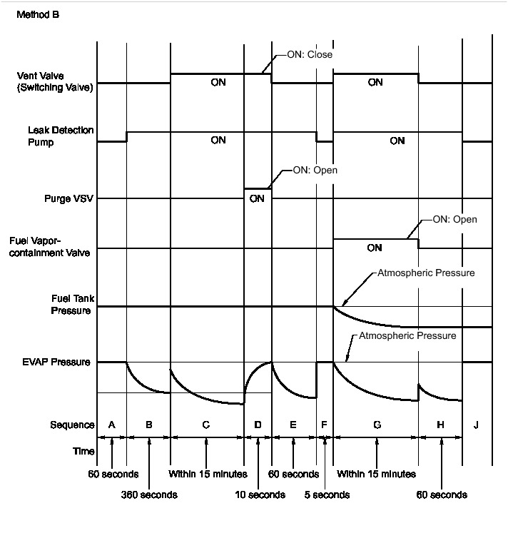
* If the fuel tank pressure is almost the same as the atmospheric pressure, vacuum will be allowed to enter the fuel tank and the system will check for leaks from the fuel tank after checking for leaks from the canister. (Method B)
HINT
*: If there is only a small amount of fuel in the fuel tank, stabilizing the EVAP pressure takes longer than usual.
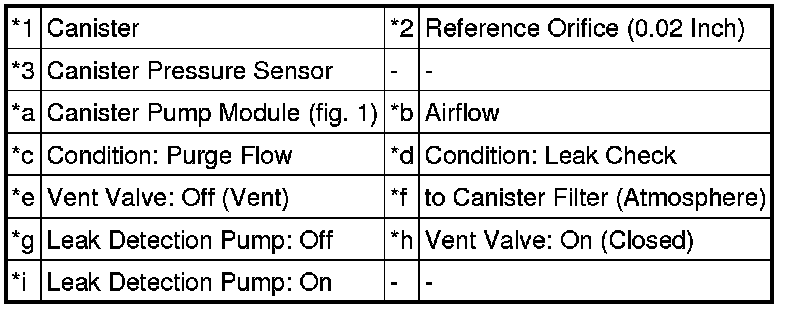
Text in Illustration
Purge Flow Monitor
The purge flow monitor consists of the 2 monitors. The 1st monitor is conducted every time and the 2nd monitor is activated if necessary.
* The 1st monitor
While the engine is running and the purge VSV (Vacuum Switching Valve) is on (open), the ECM monitors the purge flow by measuring the EVAP pressure change. If negative pressure is not created, the ECM begins the 2nd monitor.
* The 2nd monitor
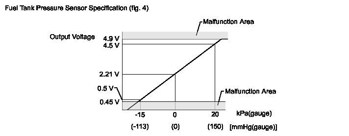
The vent valve is turned on (closed) and the EVAP pressure is then measured. If the variation in the pressure is less than 0.5 kPa(gauge) [3.751 mmHg(gauge)], the ECM interprets this as the purge VSV being stuck closed, illuminates the MIL and stores DTC P0441 (2 trip detection logic).
* Atmospheric pressure check:
In order to ensure reliable malfunction detection, the variation between the atmospheric pressures, before and after of the purge flow monitor, is measured by the ECM.
Text in Illustration
MONITOR RESULT
Refer to detailed information in Checking Monitor Status Mode 6 Data.
P2401: Evaporative System / VACUUM PMP OFF

P2402: Evaporative System / VACUUM PMP ON

P2420: Evaporative System / VENT VALVE OFF

P2419: Evaporative System / VENT VALVE ON

P043E: Evaporative System / ORIFICE CLOGGED

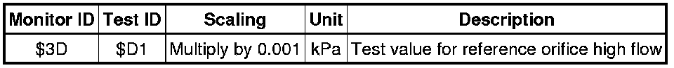
P043F: Evaporative System / ORIFICE HI-FLW
P0441: Evaporative System / PURGE VSV CLOSED

P0441: Evaporative System / PURGE VSV OPENED

P0441: Evaporative System / PURGE FLOW

P1420: Evaporative System / CNST SMALL LEAK

P1421: Evaporative System / CNST GROSS LEAK

P1422: Evaporative System / TANK SMALL LEAK

P1423: Evaporative System / TANK GROSS LEAK

P2451: Evaporative System / TANK CLS VAL OP

P2450: Evaporative System / TANK CLS VAL CL

CONFIRMATION DRIVING PATTERN
HINT
After a repair, check Monitor Status by performing the Key-Off Monitor Confirmation and Purge Flow Monitor Confirmation described below.
1. KEY-OFF MONITOR CONFIRMATION
(a) Preconditions
The monitor will not run unless:
* The vehicle has been driven for 10 minutes or more (in a city area or on a freeway).
* The fuel tank is less than 90% full.
* The altitude is less than 2400 m (7875 ft).
* The engine coolant temperature is between 4.4 and 35°C (40 and 95°F).
* The intake air temperature is between 4.4 and 35°C (40 and 95°F).
* The vehicle remains stationary (the vehicle speed is 0 km/h [0 mph]).
(b) Monitor Conditions
(1) Allow the engine to idle for at least 5 minutes.
(2) Turn the power switch off and wait for 6 hours (8 or 10.5 hours).
HINT
Do not start the engine until checking Monitor Status. If the engine is started, the steps described above must be repeated.
(c) Monitor Status
(1) Connect the Techstream to the DLC3.
(2) Turn the power switch on (IG).
(3) Turn the Techstream on.
(4) Enter the following menus: Powertrain / Engine and ECT / Monitor / Current Monitor.
(5) Check the Monitor Status displayed on the Techstream.
HINT
If Incomplete is displayed, the monitor did not complete. Make sure that the preconditions have been met, and perform the Monitor Conditions again.
2. PURGE FLOW MONITOR CONFIRMATION (P0441)
HINT
Perform this monitor confirmation after the Key-Off Monitor Confirmation shows Complete.
(a) Preconditions
The monitor will not run unless:
* The vehicle has been driven for 10 minutes or more (in a city area or on a freeway).
* The engine coolant temperature is 4.4°C (40°F) or higher.
* The intake air temperature is 4.4°C (40°F) or higher.
(b) Monitor Conditions
(1) Release the pressure from the fuel tank by removing and reinstalling the fuel tank cap assembly.
(2) Warm the engine up until the engine coolant temperature reaches higher than 75°C (167°F).
(3) Increase the engine speed to 2500 rpm once.
(4) Allow the engine to idle and turn the A/C switch on for 1 minute.
(c) Monitor Status
(1) Turn the power switch off (if on (IG) or if the engine is running).
(2) Connect the Techstream to the DLC3.
(3) Turn the power switch on (IG).
(4) Turn the Techstream on.
(5) Enter the following menus: Powertrain / Engine and ECT / Monitor / Current Monitor.
(6) Check the Monitor Status displayed on the Techstream.
HINT
If Incomplete is displayed, the monitor did not complete. Make sure that the preconditions have been met, and perform the Monitor Conditions again.
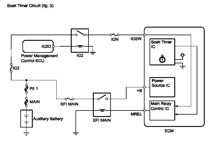
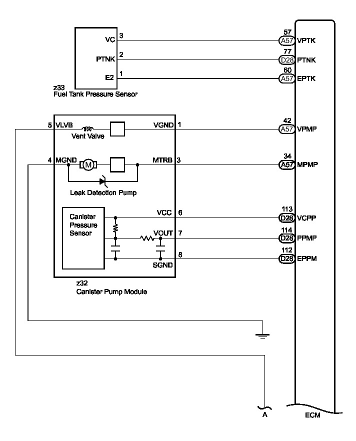
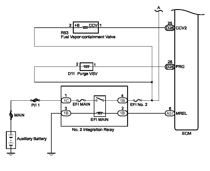
WIRING DIAGRAM
INSPECTION PROCEDURE
NOTICE:
Inspect the fuses for circuits related to this system before performing the following inspection procedure.
PROCEDURE
1. CONFIRM DTC
(a) Turn the power switch off and wait 10 seconds.
(b) Turn the power switch on (IG).
(c) Turn the power switch off and wait 10 seconds.
(d) Connect the Techstream to the DLC3.
(e) Turn the power switch on (IG) and turn the Techstream on.
(f) Enter the following menus: Powertrain / Engine and ECT / Trouble Codes.
(g) Confirm the DTCs and freeze frame data.
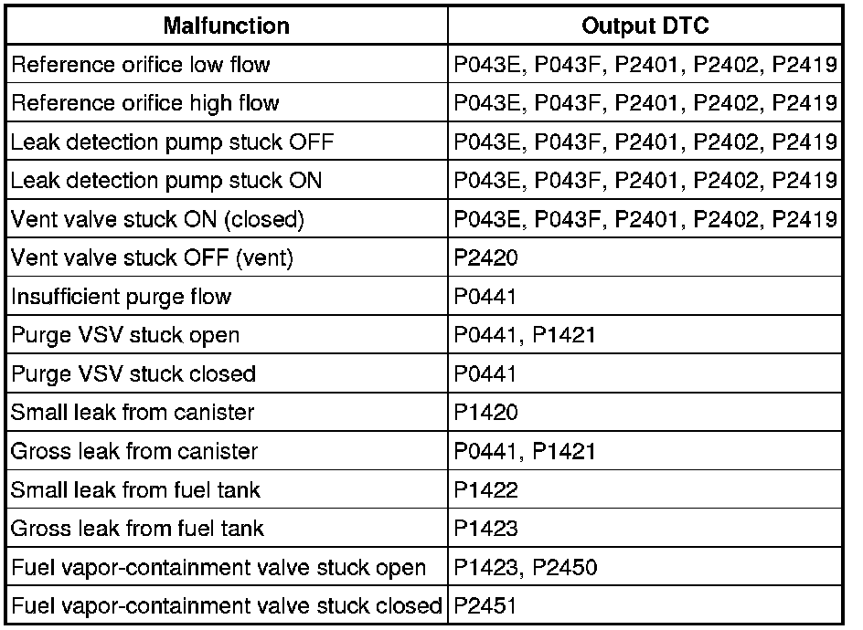
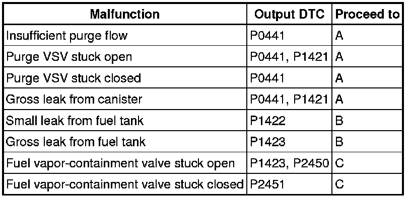
EVAP Related DTCs
DTC and Malfunction Cross-Reference
NEXT -- Continue to next step.
2. PERFORM EVAPORATIVE SYSTEM CHECK (AUTOMATIC MODE)
NOTICE:
* The Evaporative System Check (Automatic Mode) consists of 9 steps performed automatically by the Techstream. It takes a maximum of approximately 40 minutes.
* Do not perform the Evaporative System Check when the fuel tank is higher than 90% full because the cut-off valve may be closed, making the fuel tank leak check unavailable.
* Do not run the engine during this operation.
* When the temperature of the fuel is 35°C (95°F) or higher, a large amount of vapor forms and any check results become inaccurate. When performing the Evaporative System Check, keep the fuel temperature less than 35°C (95°F).
(a) Clear the DTCs.
(b) Remove the fuel tank cap and reinstall the fuel cap.
(c) Enter the following menus: Powertrain / Engine and ECT / Utility / Evaporative System Check / Automatic Mode.
(d) After the Evaporative System Check is completed, check for pending DTCs.
Result
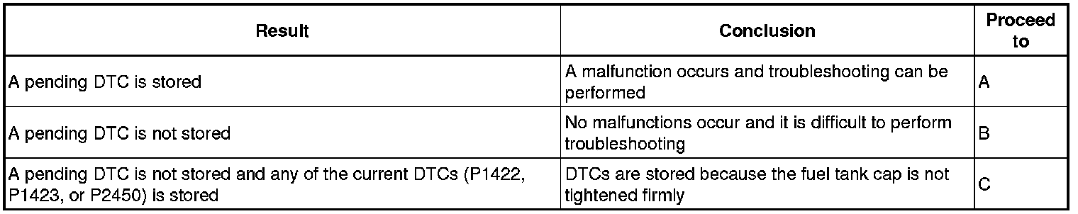
B -- PERFORM EVAPORATIVE SYSTEM CHECK (MANUAL MODE)
C -- END
A -- Continue to next step.
3. IDENTIFY TROUBLE AREAS USING DTC
(a) Refer to the table below to determine the next procedure according to the output DTCs.
Result
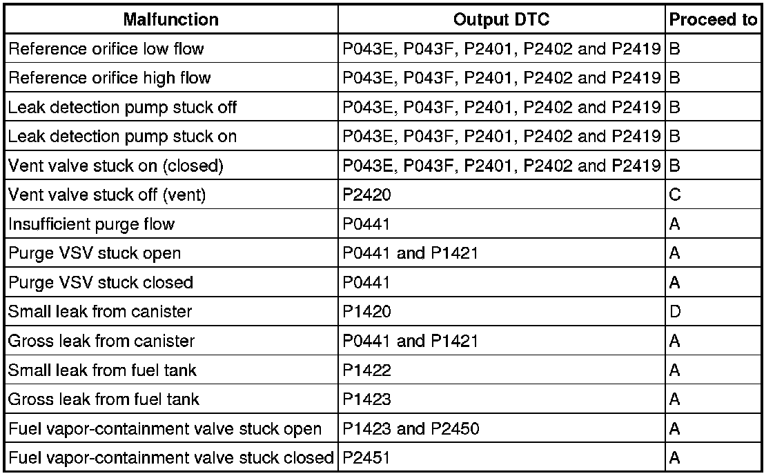
B -- PERFORM ACTIVE TEST USING TECHSTREAM (ACTIVATE THE VACUUM PUMP)
C -- CHECK CANISTER PUMP MODULE (VENT VALVE POWER SOURCE CIRCUIT)
D -- PERFORM ACTIVE TEST USING TECHSTREAM (ACTIVATE THE VSV FOR EVAP CONTROL)
A -- Continue to next step.
4. IDENTIFY TROUBLE AREAS USING DTC
(a) Refer to the table below to determine the next procedure according to the output DTCs.
Result
B -- CHECK FUEL CAP
C -- CHECK FUEL VAPOR-CONTAINMENT VALVE (POWER SOURCE CIRCUIT)
A -- Continue to next step.
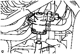
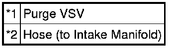
5. CHECK VACUUM HOSE (PURGE VSV - INTAKE MANIFOLD)
(a) Disconnect the hose (connected to the intake manifold) from the purge VSV.
(b) Put the engine in inspection mode (maintenance mode) Component Tests and General Diagnostics.
(c) Start the engine.
(d) Use your finger to confirm that the hose has suction.
Text in Illustration
Result
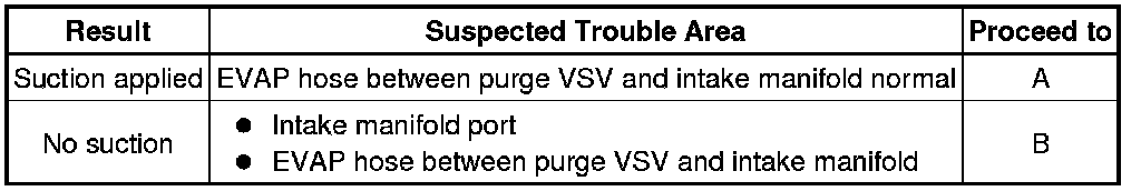
B -- INSPECT INTAKE MANIFOLD (EVAP PURGE PORT)
A -- Continue to next step.
6. PERFORM ACTIVE TEST USING TECHSTREAM (ACTIVATE THE VSV FOR EVAP CONTROL)
(a) Disconnect the hose (connected to the canister) from the purge VSV.
(b) Connect the Techstream to the DLC3.

(c) Turn the power switch on (IG).
(d) Turn the Techstream on.
(e) Put the engine in inspection mode (maintenance mode) Component Tests and General Diagnostics.
(f) Start the engine.
(g) Enter the following menus: Powertrain / Engine and ECT / Active Test / Activate the VSV for Evap Control.
(h) Using the Techstream, turn off the purge VSV (Activate the VSV for Evap Control: OFF).
(i) Use your finger to confirm that the purge VSV has no suction.
(j) Using the Techstream, turn on the purge VSV (Activate the VSV for Evap Control: ON).
(k) Use your finger to confirm that the purge VSV has suction.
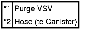
Text in Illustration
Result
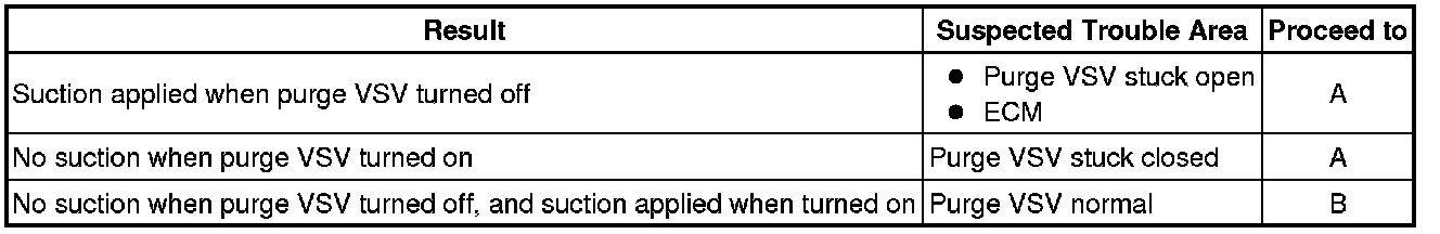
B -- CHECK HOSES (PURGE VSV - CANISTER)
A -- Continue to next step.
7. CHECK PURGE VSV
(a) Remove the purge VSV.
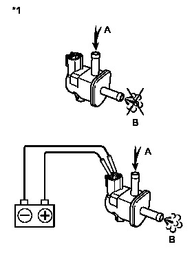
(b) Apply compressed air to the purge VSV, and confirm that no air flows from A to B as shown in the illustration.
(c) Apply auxiliary battery voltage to the purge VSV.
(d) While applying compressed air, confirm that air flows from A to B as shown in the illustration.
Text in Illustration

Result
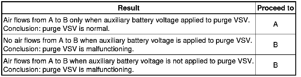
B -- REPLACE PURGE VSV
A -- Continue to next step.
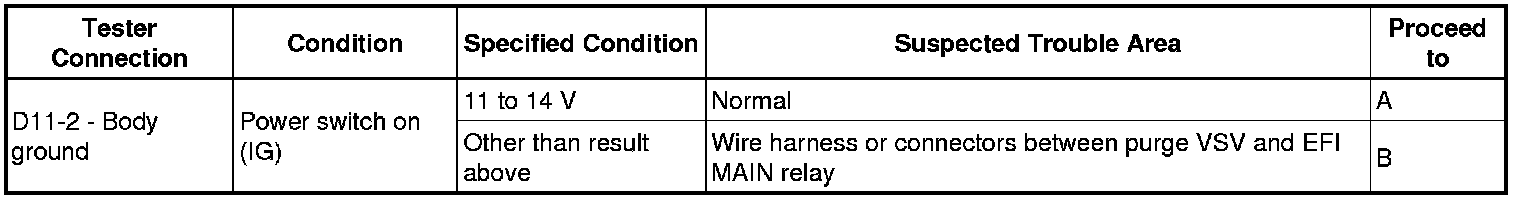
8. CHECK HARNESS AND CONNECTOR (POWER SOURCE OF PURGE VSV)
(a) Disconnect the purge VSV connector.
(b) Turn the power switch on (IG).
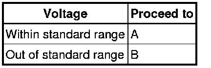
(c) Measure the voltage according to the value(s) in the table below.
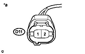
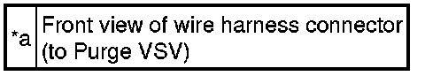
Text in Illustration
Result
B -- REPAIR OR REPLACE HARNESS OR CONNECTOR
A -- Continue to next step.
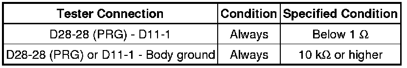
9. CHECK HARNESS AND CONNECTOR (PURGE VSV - ECM)
(a) Disconnect the ECM connector.
(b) Disconnect the purge VSV connector.
(c) Measure the resistance according to the value(s) in the table below.
Standard Resistance (Check for Open):
NG -- REPAIR OR REPLACE HARNESS OR CONNECTOR
OK -- Continue to next step.
10. REPLACE ECM
(a) Replace the ECM Removal.
NEXT -- PERFORM EVAPORATIVE SYSTEM CHECK AGAIN (AUTOMATIC MODE)
11. PERFORM ACTIVE TEST USING TECHSTREAM (ACTIVATE THE VACUUM PUMP)
(a) Connect the Techstream to DLC3.
(b) Turn the power switch on (IG).
(c) Enter the following menus: Powertrain / Engine and ECT / Active Test / Activate the Vacuum Pump.
(d) Turn the vacuum pump (leak detection pump) on with the Techstream.
(e) Touch the canister pump module and check if the pump is moving.
OK:
Pump operates
NG -- CHECK CANISTER PUMP MODULE (LEAK DETECTION PUMP POWER SOURCE CIRCUIT)
OK -- Continue to next step.
12. PERFORM ACTIVE TEST USING TECHSTREAM (ACTIVATE THE VSV FOR VENT VALVE)
(a) Connect the Techstream to DLC3.
(b) Turn the power switch on (IG).
(c) Enter the following menus: Powertrain / Engine and ECT / Active Test / Activate the VSV for Vent Valve.
(d) Touch the canister pump module, use the Techstream to turn the vent valve ON and OFF, and check if the vent valve is moving.
OK:
Vent valve vibration can be felt.
OK -- REPLACE CANISTER
NG -- CHECK CANISTER PUMP MODULE (VENT VALVE POWER SOURCE CIRCUIT)
13. CHECK CANISTER PUMP MODULE (LEAK DETECTION PUMP POWER SOURCE CIRCUIT)
(a) Disconnect the canister pump module connector.
(b) Connect the Techstream to the DLC3.
(c) Turn the power switch on (IG).
(d) Enter the following menus: Powertrain / Engine and ECT / Active Test / Activate the Vacuum Pump.
(e) Turn the vacuum pump (leak detection pump) on using the Techstream.
(f) Measure the voltage according to the value(s) in the table below.
Standard Voltage:
Text in Illustration
Result
B -- REPLACE CANISTER
A -- Continue to next step.
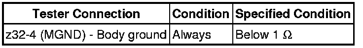
14. CHECK HARNESS AND CONNECTOR (CANISTER PUMP MODULE - BODY GROUND)
(a) Disconnect the canister pump module connector.
(b) Measure the resistance according to the value(s) in the table below.
Standard Resistance:
NG -- REPAIR OR REPLACE HARNESS OR CONNECTOR
OK -- Continue to next step.
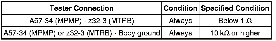
15. CHECK HARNESS AND CONNECTOR (CANISTER PUMP MODULE - ECM)
(a) Disconnect the ECM connector.
(b) Disconnect the canister pump module connector.
(c) Measure the resistance according to the value(s) in the table below.
Standard Resistance (Check for Open):
NG -- REPAIR OR REPLACE HARNESS OR CONNECTOR
OK -- Continue to next step.
16. REPLACE ECM
(a) Replace the ECM Removal.
NEXT -- PERFORM EVAPORATIVE SYSTEM CHECK AGAIN (AUTOMATIC MODE)
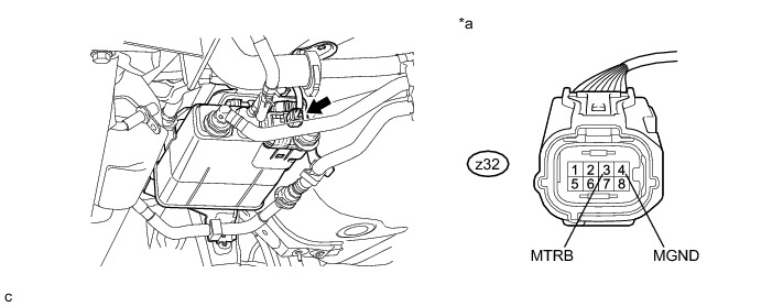
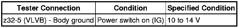
17. CHECK CANISTER PUMP MODULE (VENT VALVE POWER SOURCE CIRCUIT)
(a) Disconnect the canister pump module connector.
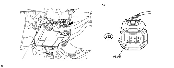
(b) Turn the power switch on (IG).
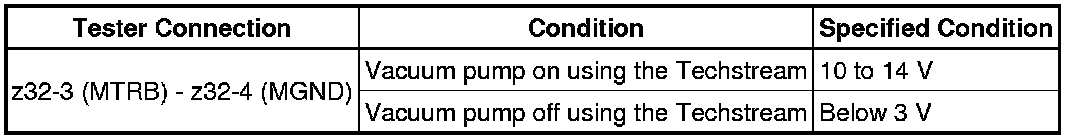
(c) Measure the voltage according to the value(s) in the table below.
Standard Voltage:
Text in Illustration

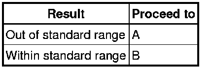
Result
B -- REPAIR OR REPLACE HARNESS OR CONNECTOR
A -- Continue to next step.
18. INSPECT CANISTER PUMP MODULE (VENT VALVE OPERATION)
(a) Disconnect the canister pump module connector.
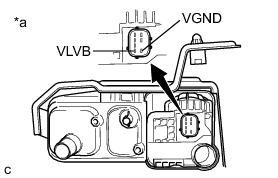
(b) Apply auxiliary battery voltage to VLVB and VGND terminals of the canister pump module.
(c) Touch the canister pump module to confirm the vent valve operation.
Text in Illustration
Result
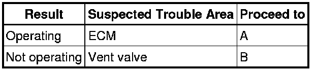
B -- REPLACE CANISTER
A -- Continue to next step.
19. REPLACE ECM
(a) Replace the ECM Removal.
NEXT -- PERFORM EVAPORATIVE SYSTEM CHECK AGAIN (AUTOMATIC MODE)
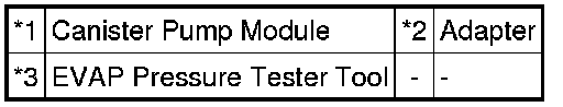
20. CHECK HOSES (PURGE VSV - CANISTER)
(a) Connect the EVAP pressure tester tool to the canister pump module with the adapter.
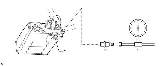
Text in Illustration
(b) Confirm good connection at the canister pump module.
(c) Pressurize the EVAP system to between 3.2 and 3.7 kPa(gauge) [24 and 28 mmHg(gauge)].
NOTICE:
Higher than 4.7 kPa(gauge) [35 mmHg(gauge)] of pressure will damage the EVAP system. Pay attention to the pressure.
(d) Apply soapy water to the piping and connections of the EVAP system.
(e) Look for areas where bubbles appear.
HINT
If the system has leaks, a whistling sound will be heard.
NEXT -- Continue to next step.