Part 2
2ZR-FXE ENGINE CONTROL: SFI SYSTEM: EVAP System
- EVAP System (Continued..)
21. REPLACE MALFUNCTIONING PART
(a) Repair or replace the leak point.
NEXT -- PERFORM EVAPORATIVE SYSTEM CHECK AGAIN (AUTOMATIC MODE)
22. CHECK FUEL CAP
(a) Check that the fuel cap is correctly installed and confirm that the fuel cap meets OEM specifications.
(b) Tighten the fuel cap until a few click sounds are heard.
HINT
If an EVAP tester is available, check the fuel cap using the tester.
(1) Remove the fuel cap and install it onto a fuel cap adapter.
(2) Connect an EVAP tester pump hose to the adapter, and pressurize the cap to 3.2 to 3.7 kPa(gauge) [24 to 27.75 mmHg(gauge)] using an EVAP tester pump.
(3) Seal the adapter and wait for 2 minutes.
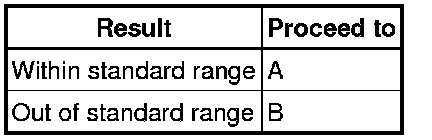
(4) Check the pressure. If the pressure is 2 kPa(gauge) [15 mmHg(gauge)] or higher, the fuel cap is normal.
Result
B -- REPLACE FUEL CAP
A -- Continue to next step.
23. CHECK HOSES (FUEL VAPOR-CONTAINMENT VALVE - FUEL TANK)
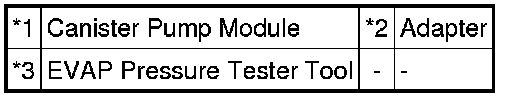
(a) Connect the EVAP pressure tester tool to the canister pump module with the adapter.
Text in Illustration

(b) Connect the Techstream to the DLC3.
(c) Turn the power switch on (IG).
(d) Turn the Techstream on.
(e) Enter the following menus: Powertrain / Engine and ECT / Active Test / Activate the Fuel Vapor-Containment Valve.
(f) Turn the fuel vapor-containment valve ON using the Techstream.
(g) Confirm good connection at the canister pump module.
(h) Pressurize the EVAP system to between 3.2 and 3.7 kPa(gauge) [24 and 28 mmHg(gauge)].
NOTICE:
Higher than 4.7 kPa(gauge) [35 mmHg(gauge)] of pressure will damage the EVAP system. Pay attention to the pressure.
(i) Apply soapy water to the piping and connections of the EVAP system.
(j) Look for areas where bubbles appear.
HINT
If the system has leaks, a whistling sound will be heard.
NEXT -- Continue to next step.
24. REPLACE MALFUNCTIONING PART
(a) Repair or replace the leak point.
NEXT -- PERFORM EVAP SYSTEM CHECK AGAIN (AUTO OPERATION)
25. CHECK FUEL VAPOR-CONTAINMENT VALVE (POWER SOURCE CIRCUIT)
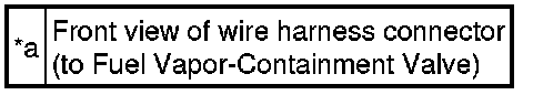
(a) Disconnect the fuel vapor-containment valve connector.
(b) Turn the power switch on (IG).
(c) Measure the voltage according to the value(s) in the table below.
Text in Illustration

Standard Voltage:
NG -- REPAIR OR REPLACE HARNESS OR CONNECTOR
OK -- Continue to next step.
26. INSPECT FUEL VAPOR-CONTAINMENT VALVE
(a) Inspect the fuel vapor-containment valve Testing and Inspection.
NG -- REPLACE FUEL VAPOR-CONTAINMENT VALVE
OK -- Continue to next step.
27. CHECK HARNESS AND CONNECTOR (FUEL VAPOR-CONTAINMENT VALVE - ECM)
(a) Disconnect the ECM connector.
(b) Disconnect the fuel vapor-containment valve connector.
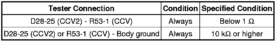
(c) Measure the resistance according to the value(s) in the table below.
Standard Resistance (Check for Open):

NG -- REPAIR OR REPLACE HARNESS OR CONNECTOR
OK -- Continue to next step.
28. REPLACE ECM
(a) Replace the ECM Removal.
NEXT -- PERFORM EVAPORATIVE SYSTEM CHECK AGAIN (AUTOMATIC MODE)
29. REPLACE PURGE VSV
(a) Replace the purge VSV Removal.
NEXT -- PERFORM EVAPORATIVE SYSTEM CHECK AGAIN (AUTOMATIC MODE)
30. REPLACE CANISTER
(a) Replace the canister Removal.
NEXT -- PERFORM EVAPORATIVE SYSTEM CHECK AGAIN (AUTOMATIC MODE)
31. REPLACE FUEL VAPOR-CONTAINMENT VALVE
(a) Replace the fuel vapor-containment valve Removal.
NEXT -- PERFORM EVAPORATIVE SYSTEM CHECK AGAIN (AUTOMATIC MODE)
32. REPLACE FUEL CAP
(a) Replace the fuel cap.
NEXT -- PERFORM EVAPORATIVE SYSTEM CHECK AGAIN (AUTOMATIC MODE)
33. INSPECT INTAKE MANIFOLD (EVAP PURGE PORT)
(a) Disconnect the EVAP hose from the intake manifold.
(b) Connect the Techstream to the DLC3.
(c) Turn the power switch on (IG).
(d) Turn the Techstream on.
(e) Put the engine in inspection mode (maintenance mode) Component Tests and General Diagnostics.
(f) Start the engine.
(g) Use your finger to confirm that the port of the intake manifold has suction.
Result
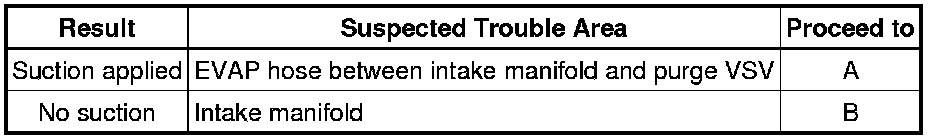
B -- REPAIR OR REPLACE INTAKE MANIFOLD (EVAP PURGE PORT)
A -- Continue to next step.
34. REPAIR OR REPLACE EVAP HOSE (INTAKE MANIFOLD - PURGE VSV)
(a) Repair or replace the EVAP hose.
NEXT -- PERFORM EVAPORATIVE SYSTEM CHECK AGAIN (AUTOMATIC MODE)
35. REPAIR OR REPLACE INTAKE MANIFOLD (EVAP PURGE PORT)
(a) Check that the EVAP purge port of the intake manifold is not clogged. If necessary, replace the intake manifold.
NEXT -- PERFORM EVAPORATIVE SYSTEM CHECK AGAIN (AUTOMATIC MODE)
36. REPAIR OR REPLACE HARNESS OR CONNECTOR
(a) Repair or replace harness or connector.
NEXT -- PERFORM EVAPORATIVE SYSTEM CHECK AGAIN (AUTOMATIC MODE)
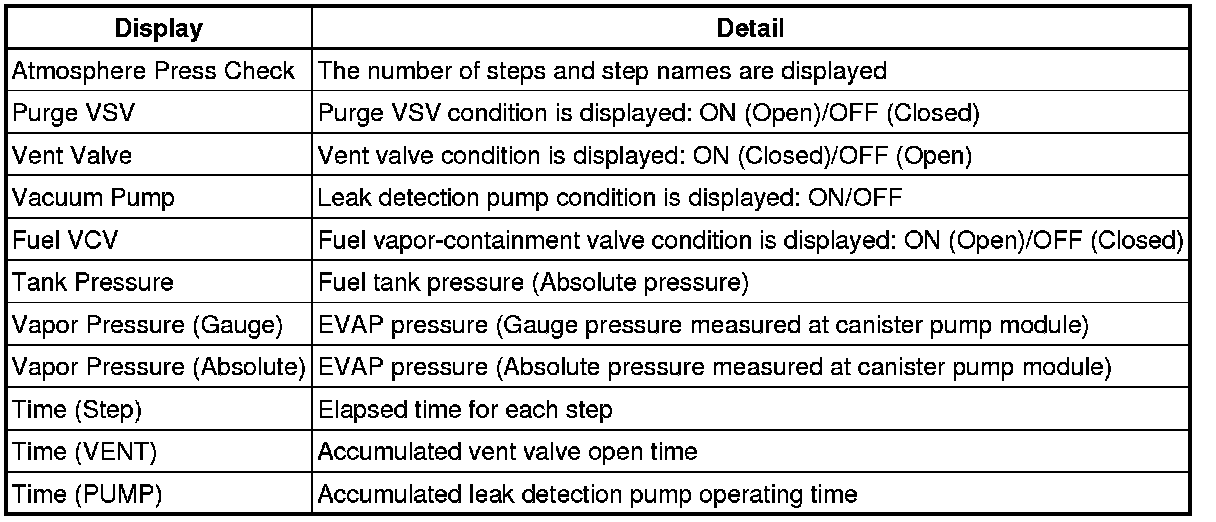
37. PERFORM EVAPORATIVE SYSTEM CHECK (MANUAL MODE)
HINT
In the manual operation check, the EVAP system can be checked in several steps. Valve operation and pressure in each step can also be checked.
(a) Clear the DTCs Reading and Clearing Diagnostic Trouble Codes.
(b) Remove the fuel tank cap and reinstall the fuel tank cap.
(c) Enter the following menus: Powertrain / Engine and ECT / Utility / Evaporative System Check / Manual Mode.
NOTICE:
* The Evaporative System Check (Automatic Mode) consists of 9 steps performed automatically by the Techstream. It takes a maximum of approximately 40 minutes.
* Do not perform the Evaporative System Check when the fuel tank is higher than 90% full because the cut-off valve may be closed, making the fuel tank leak check unavailable.
* Do not run the engine during this operation.
* When the temperature of the fuel is 35°C (95°F) or higher, a large amount of vapor forms and any check results become inaccurate. When performing the Evaporative System Check, keep the fuel temperature less than 35°C (95°F).
Techstream Display
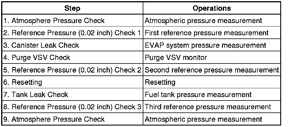
Manual Operation Step
NEXT -- Continue to next step.
38. PERFORM EVAPORATIVE SYSTEM CHECK (MANUAL MODE STEP 1)
(a) Select step 1 and wait 10 seconds.
NEXT -- Continue to next step.
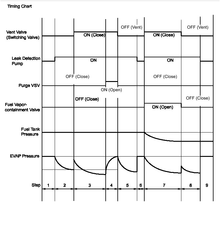
39. PERFORM EVAPORATIVE SYSTEM CHECK (MANUAL MODE STEP 2)
(a) Perform step 2.
(b) Check the evaporative pressure 2 seconds after the leak detection pump is activated*. (step b)
*: The leak detection pump begins to operate at the start of step 2.
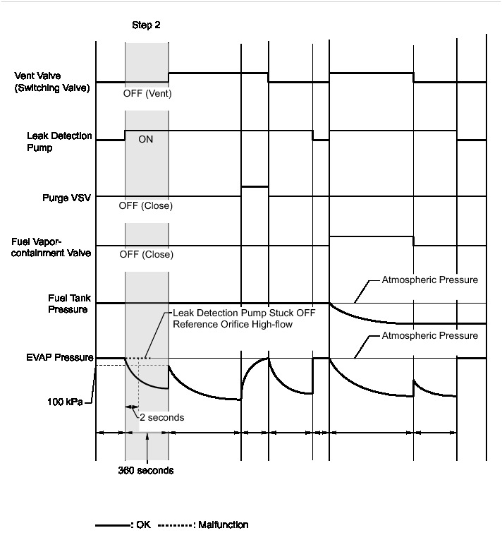
(c) Check the evaporative (EVAP) pressure again when it has stabilized. This pressure is the first reference pressure.
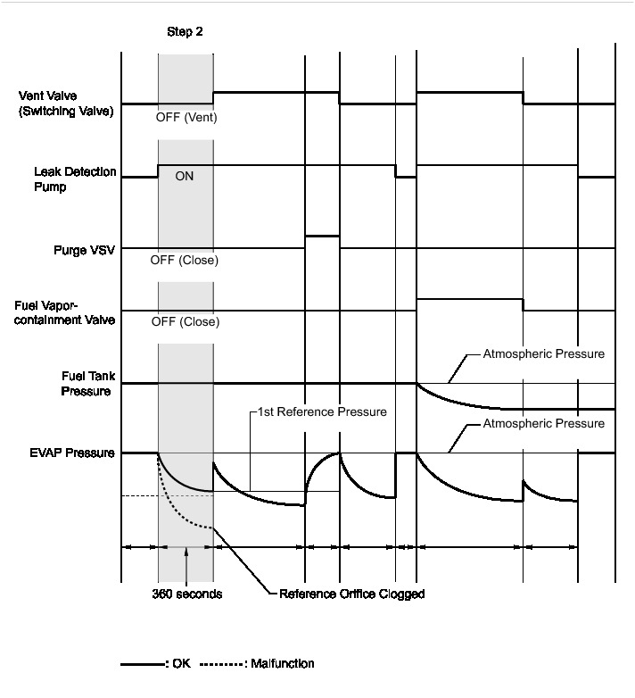
Result
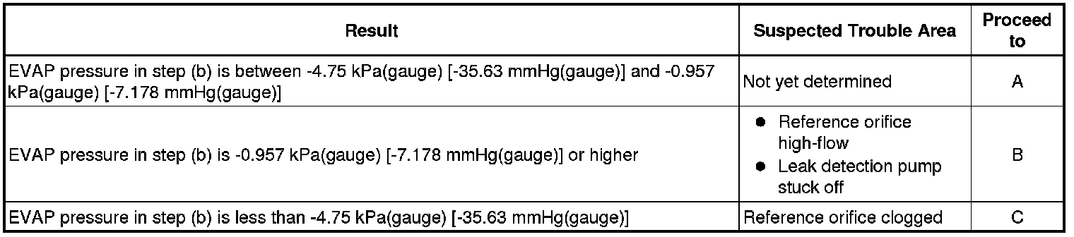
B -- PERFORM ACTIVE TEST USING TECHSTREAM (ACTIVATE THE VACUUM PUMP)
C -- REPLACE CANISTER
A -- Continue to next step.
40. PERFORM EVAPORATIVE SYSTEM CHECK (MANUAL MODE STEP 3)
(a) Perform step 3.
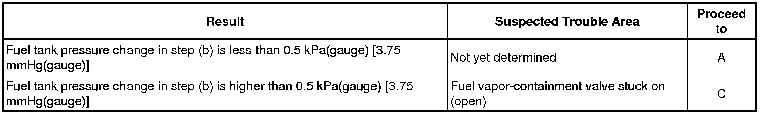
(b) Check the evaporative (EVAP) pressure change in step 3. (step b)
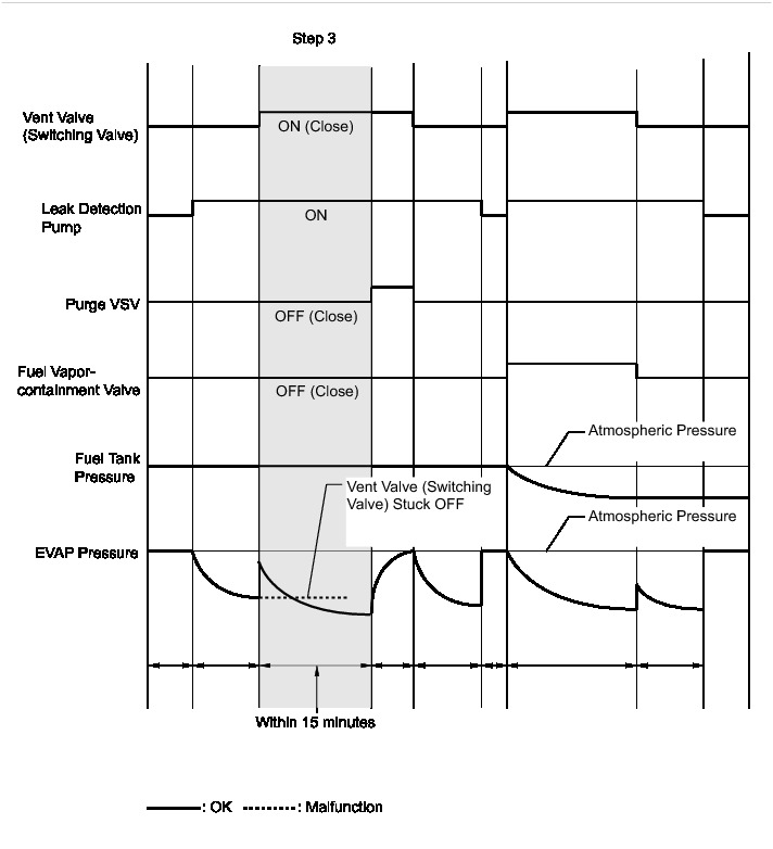
Result

(c) Check the fuel tank pressure change in step 3.
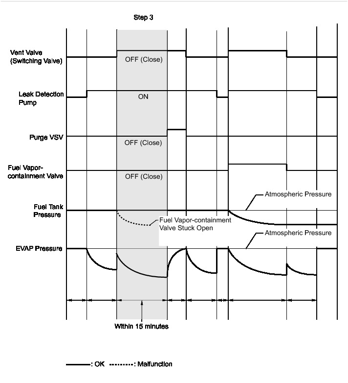
Result
(d) Check the EVAP pressure again when it has stabilized. This pressure is the canister leak pressure.
(e) Compare the first reference pressure with the canister leak pressure.
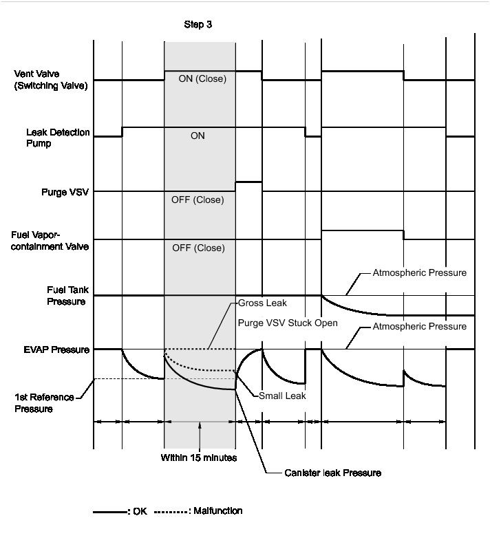
Result
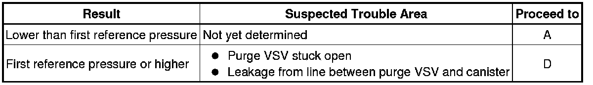
B -- CHECK CANISTER PUMP MODULE (VENT VALVE POWER SOURCE CIRCUIT)
C -- CHECK FUEL VAPOR-CONTAINMENT VALVE (POWER SOURCE CIRCUIT)
D -- CHECK HOSES (PURGE VSV - CANISTER)
A -- Continue to next step.
41. PERFORM EVAPORATIVE SYSTEM CHECK (MANUAL MODE STEP 4)
(a) Perform step 4.
(b) Check the evaporative (EVAP) pressure change in step 4. (step b)
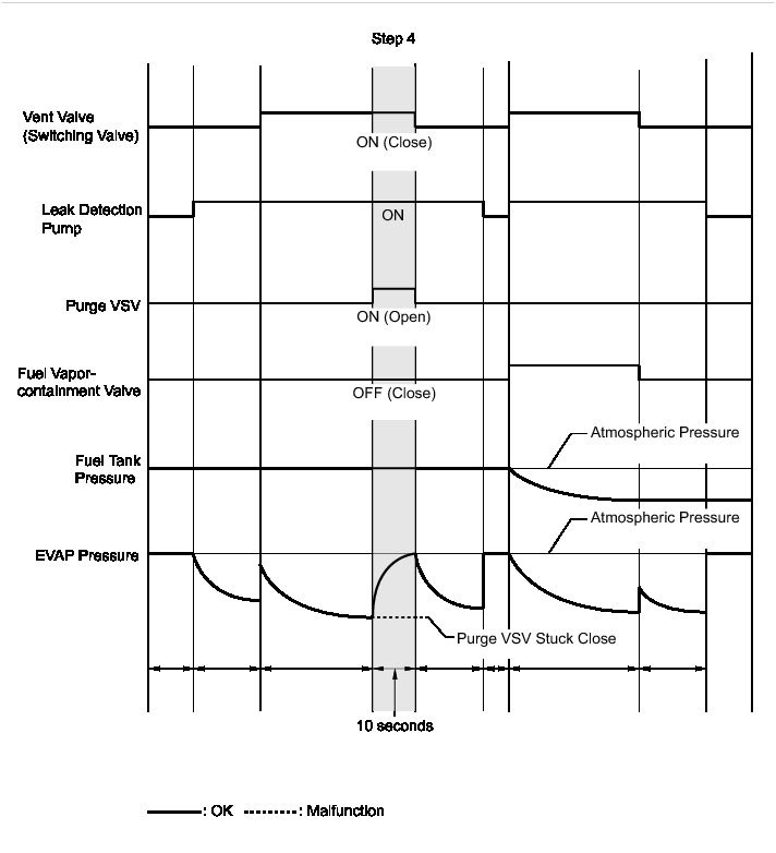
Result
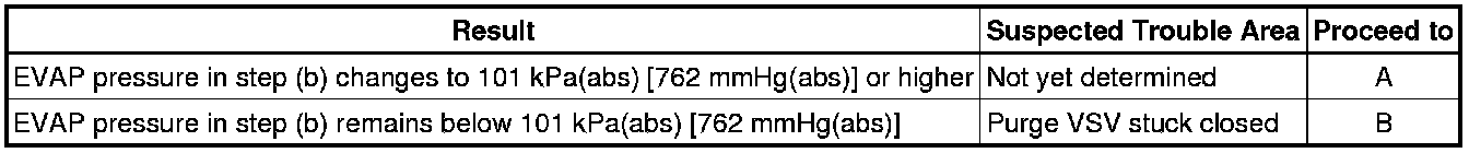
B -- CHECK VACUUM HOSE (PURGE VSV - INTAKE MANIFOLD)
A -- Continue to next step.
42. PERFORM EVAPORATIVE SYSTEM CHECK (MANUAL MODE STEP 5)
(a) Perform step 5 and wait 60 seconds.
(b) Check the evaporative (EVAP) pressure. This pressure is the second reference pressure.
NEXT -- Continue to next step.
43. PERFORM EVAPORATIVE SYSTEM CHECK (MANUAL MODE STEP 6)
(a) Perform step 6 and wait 5 seconds.
NEXT -- Continue to next step.
44. PERFORM EVAPORATIVE SYSTEM CHECK (MANUAL MODE STEP 7)
(a) Perform step 7.
(b) Check that the tank pressure and EVAP pressure change.
(c) Check the tank pressure again when it has stabilized. This pressure is the fuel tank leak pressure.
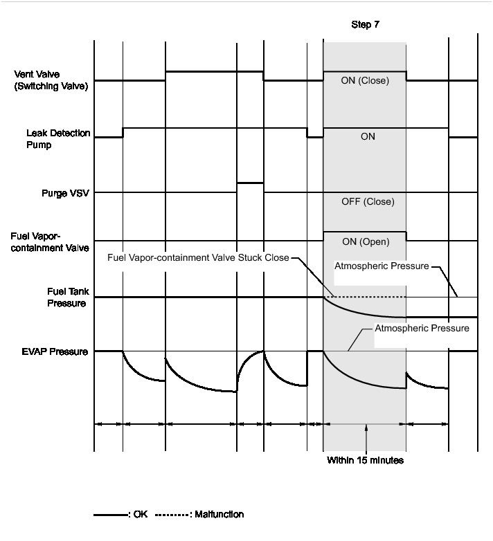
Result
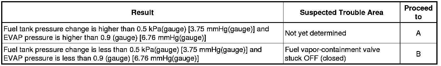
B -- CHECK FUEL VAPOR-CONTAINMENT VALVE (POWER SOURCE CIRCUIT)
A -- Continue to next step.
45. PERFORM EVAPORATIVE SYSTEM CHECK (MANUAL MODE STEP 8)
(a) Perform step 8 and wait 60 seconds.
(b) Check the evaporative (EVAP) pressure. This pressure is the third reference pressure.
(c) Compare the fuel tank pressure checked in step 7 with the third reference pressure.
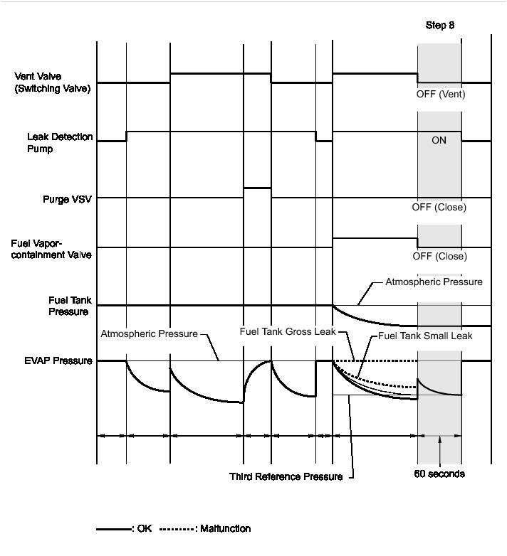
Result
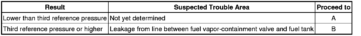
B -- CHECK FUEL CAP
A -- Continue to next step.
46. PERFORM CONFIRMATION DRIVING PATTERN
(a) Refer to Confirmation Driving Pattern.
NEXT -- PERFORM EVAPORATIVE SYSTEM CHECK AGAIN (AUTOMATIC MODE)
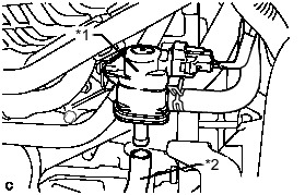
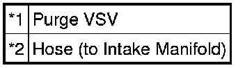
47. CHECK VACUUM HOSE (PURGE VSV - INTAKE MANIFOLD)
(a) Disconnect the hose (connected to the intake manifold) from the purge VSV.
(b) Put the engine in inspection mode (maintenance mode) Component Tests and General Diagnostics.
(c) Start the engine.
(d) Use your finger to confirm that the hose has suction.
Text in Illustration
Result
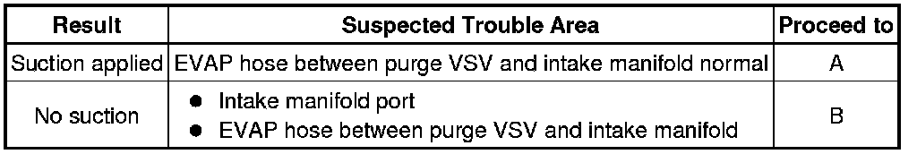
B -- INSPECT INTAKE MANIFOLD (EVAP PURGE PORT)
A -- Continue to next step.
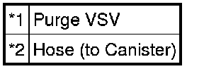
48. PERFORM ACTIVE TEST USING TECHSTREAM (ACTIVATE THE VSV FOR EVAP CONTROL)
(a) Disconnect the hose (connected to the canister) from the purge VSV.
(b) Connect the Techstream to the DLC3.

(c) Turn the power switch on (IG).
(d) Turn the Techstream on.
(e) Put the engine in inspection mode (maintenance mode) Component Tests and General Diagnostics.
(f) Start the engine.
(g) Enter the following menus: Powertrain / Engine and ECT / Active Test / Activate the VSV for Evap Control.
(h) Using the Techstream, turn off the purge VSV (Activate the VSV for Evap Control: OFF).
(i) Use your finger to confirm that the purge VSV has no suction.
(j) Using the Techstream, turn on the purge VSV (Activate the VSV for Evap Control: ON).
(k) Use your finger to confirm that the purge VSV has suction.
Text in Illustration
Result
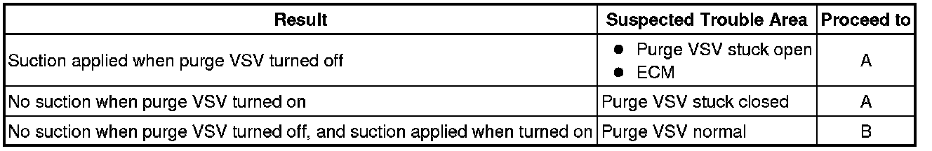
B -- CHECK HOSES (PURGE VSV - CANISTER)
A -- Continue to next step.
49. CHECK PURGE VSV
(a) Remove the purge VSV.
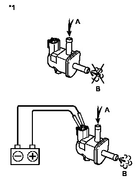
(b) Apply compressed air to the purge VSV, and confirm that no air flows from A to B as shown in the illustration.
(c) Apply auxiliary battery voltage to the purge VSV.
(d) While applying compressed air, confirm that air flows from A to B as shown in the illustration.
Text in Illustration

Result
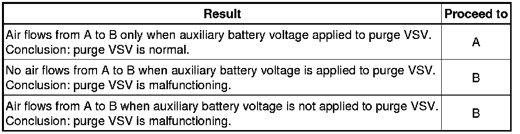
B -- REPLACE PURGE VSV
A -- Continue to next step.
50. CHECK HARNESS AND CONNECTOR (POWER SOURCE OF PURGE VSV)
(a) Disconnect the purge VSV connector.
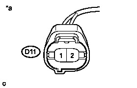
(b) Turn the power switch on (IG).
(c) Measure the voltage according to the value(s) in the table below.
Text in Illustration
Result
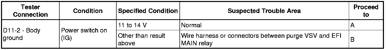
B -- REPAIR OR REPLACE HARNESS OR CONNECTOR
A -- Continue to next step.
51. CHECK HARNESS AND CONNECTOR (PURGE VSV - ECM)
(a) Disconnect the ECM connector.
(b) Disconnect the purge VSV connector.
(c) Measure the resistance according to the value(s) in the table below.
Standard Resistance (Check for Open):
NG -- REPAIR OR REPLACE HARNESS OR CONNECTOR
OK -- Continue to next step.
52. REPLACE ECM
(a) Replace the ECM Removal.
NEXT -- PERFORM EVAPORATIVE SYSTEM CHECK AGAIN (AUTOMATIC MODE)
53. PERFORM ACTIVE TEST USING TECHSTREAM (ACTIVATE THE VACUUM PUMP)
(a) Connect the Techstream to DLC3.
(b) Turn the power switch on (IG).
(c) Enter the following menus: Powertrain / Engine and ECT / Active Test / Activate the Vacuum Pump.
(d) Turn the vacuum pump (leak detection pump) on with the Techstream.
(e) Touch the canister pump module and check if the pump is moving.
OK:
Pump operates
NG -- CHECK CANISTER PUMP MODULE (LEAK DETECTION PUMP POWER SOURCE CIRCUIT)
OK -- Continue to next step.
54. PERFORM ACTIVE TEST USING TECHSTREAM (ACTIVATE THE VSV FOR VENT VALVE)
(a) Connect the Techstream to DLC3.
(b) Turn the power switch on (IG).
(c) Enter the following menus: Powertrain / Engine and ECT / Active Test / Activate the VSV for Vent Valve.
(d) Touch the canister pump module, use the Techstream to turn the vent valve ON and OFF, and check if the vent valve is moving.
OK:
Vent valve vibration can be felt.
OK -- REPLACE CANISTER
NG -- CHECK CANISTER PUMP MODULE (VENT VALVE POWER SOURCE CIRCUIT)
55. CHECK CANISTER PUMP MODULE (LEAK DETECTION PUMP POWER SOURCE CIRCUIT)
(a) Disconnect the canister pump module connector.
(b) Connect the Techstream to the DLC3.
(c) Turn the power switch on (IG).
(d) Enter the following menus: Powertrain / Engine and ECT / Active Test / Activate the Vacuum Pump.
(e) Turn the vacuum pump (leak detection pump) on using the Techstream.
(f) Measure the voltage according to the value(s) in the table below.
Standard Voltage:
Text in Illustration
Result

B -- REPLACE CANISTER
A -- Continue to next step.
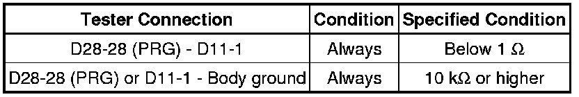
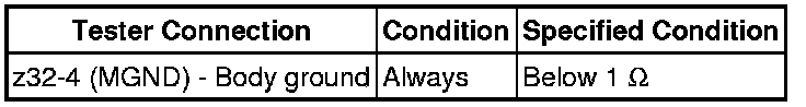
56. CHECK HARNESS AND CONNECTOR (CANISTER PUMP MODULE - BODY GROUND)
(a) Disconnect the canister pump module connector.
(b) Measure the resistance according to the value(s) in the table below.
Standard Resistance:
NG -- REPAIR OR REPLACE HARNESS OR CONNECTOR
OK -- Continue to next step.
57. CHECK HARNESS AND CONNECTOR (CANISTER PUMP MODULE - ECM)
(a) Disconnect the ECM connector.
(b) Disconnect the canister pump module connector.
(c) Measure the resistance according to the value(s) in the table below.
Standard Resistance (Check for Open):
NG -- REPAIR OR REPLACE HARNESS OR CONNECTOR
OK -- Continue to next step.
58. REPLACE ECM
(a) Replace the ECM Removal.
NEXT -- PERFORM EVAPORATIVE SYSTEM CHECK AGAIN (AUTOMATIC MODE)
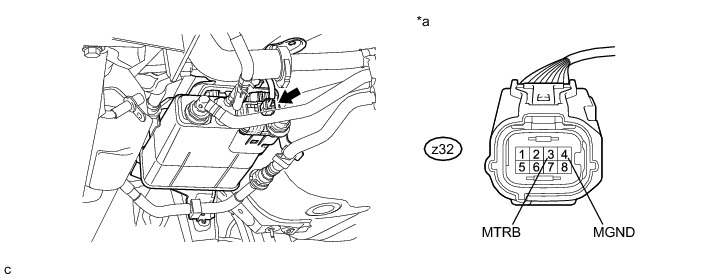
59. CHECK CANISTER PUMP MODULE (VENT VALVE POWER SOURCE CIRCUIT)
(a) Disconnect the canister pump module connector.
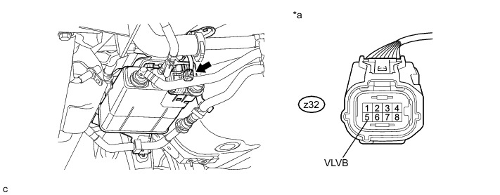
(b) Turn the power switch on (IG).
(c) Measure the voltage according to the value(s) in the table below.
Standard Voltage:
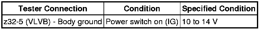
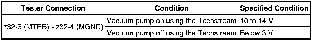
Text in Illustration

Result
B -- REPAIR OR REPLACE HARNESS OR CONNECTOR
A -- Continue to next step.
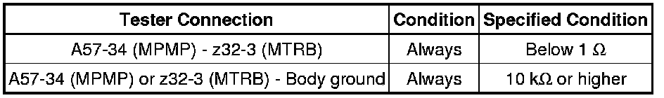
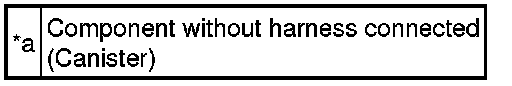
60. CHECK HARNESS AND CONNECTOR (VENT VALVE - BODY GROUND)
(a) Disconnect the canister pump module connector.
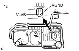
(b) Apply auxiliary battery voltage to VLVB and VGND terminals of the canister pump module.
(c) Touch the canister pump module to confirm the vent valve operation.
Text in Illustration
Result
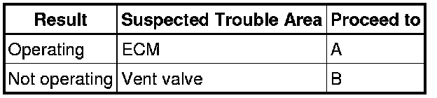
B -- REPLACE CANISTER
A -- Continue to next step.
61. REPLACE ECM
(a) Replace the ECM Removal.
NEXT -- PERFORM EVAPORATIVE SYSTEM CHECK AGAIN (AUTOMATIC MODE)
62. CHECK HOSES (PURGE VSV - CANISTER)
(a) Connect the EVAP pressure tester tool to the canister pump module with the adapter.
Text in Illustration

(b) Confirm good connection at the canister pump module.
(c) Pressurize the EVAP system to between 3.2 and 3.7 kPa(gauge) [24 and 28 mmHg(gauge)].
NOTICE:
Higher than 4.7 kPa(gauge) [35 mmHg(gauge)] of pressure will damage the EVAP system. Pay attention to the pressure.
(d) Apply soapy water to the piping and connections of the EVAP system.
(e) Look for areas where bubbles appear.
HINT
If the system has leaks, a whistling sound will be heard.
NEXT -- Continue to next step.
63. REPLACE MALFUNCTIONING PART
(a) Repair or replace the leak point.
NEXT -- PERFORM EVAPORATIVE SYSTEM CHECK AGAIN (AUTOMATIC MODE)
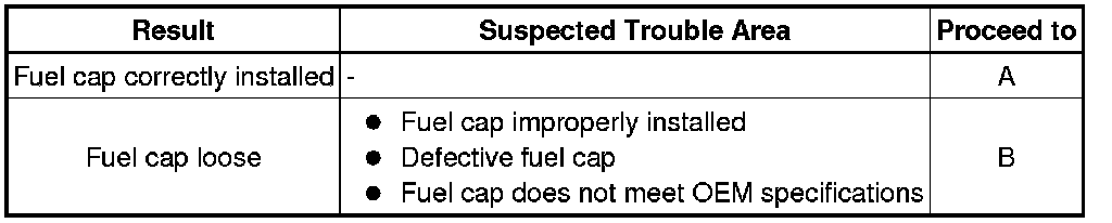
64. CHECK FUEL CAP
(a) Check that the fuel cap is correctly installed and confirm that the fuel cap meets OEM specifications.
(b) Tighten the fuel cap until a few click sounds are heard.
HINT
If an EVAP tester is available, check the fuel cap using the tester.
(1) Remove the fuel cap and install it onto a fuel cap adapter.
(2) Connect an EVAP tester pump hose to the adapter, and pressurize the cap to 3.2 to 3.7 kPa(gauge) [24 to 27.75 mmHg(gauge)] using an EVAP tester pump.
(3) Seal the adapter and wait for 2 minutes.
(4) Check the pressure. If the pressure is 2 kPa(gauge) [15 mmHg(gauge)] or higher, the fuel cap is normal.
Result

B -- REPLACE FUEL CAP
A -- Continue to next step.
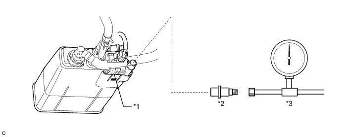
65. CHECK HOSES (FUEL VAPOR-CONTAINMENT VALVE - FUEL TANK)
(a) Connect the EVAP pressure tester tool to the canister pump module with the adapter.
Text in Illustration
(b) Connect the Techstream to the DLC3.
(c) Turn the power switch on (IG).
(d) Turn the Techstream on.
(e) Enter the following menus: Powertrain / Engine and ECT / Active Test / Activate the Fuel Vapor-Containment Valve.
(f) Turn the fuel vapor-containment valve ON using the Techstream.
(g) Confirm good connection at the canister pump module.
(h) Pressurize the EVAP system to between 3.2 and 3.7 kPa(gauge) [24 and 28 mmHg(gauge)].
NOTICE:
Higher than 4.7 kPa(gauge) [35 mmHg(gauge)] of pressure will damage the EVAP system. Pay attention to the pressure.
(i) Apply soapy water to the piping and connections of the EVAP system.
(j) Look for areas where bubbles appear.
HINT
If the system has leaks, a whistling sound will be heard.
NEXT -- Continue to next step.
66. REPLACE MALFUNCTIONING PART
(a) Repair or replace the leak point.
NEXT -- PERFORM EVAP SYSTEM CHECK AGAIN (AUTO OPERATION)
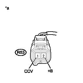
67. CHECK FUEL VAPOR-CONTAINMENT VALVE (POWER SOURCE CIRCUIT)
(a) Disconnect the fuel vapor-containment valve connector.
(b) Turn the power switch on (IG).
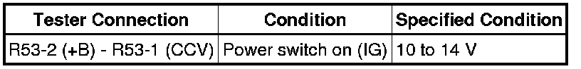
(c) Measure the voltage according to the value(s) in the table below.
Text in Illustration
Standard Voltage:

NG -- REPAIR OR REPLACE HARNESS OR CONNECTOR
OK -- Continue to next step.
68. INSPECT FUEL VAPOR-CONTAINMENT VALVE
(a) Inspect the fuel vapor-containment valve Testing and Inspection.
NG -- REPLACE FUEL VAPOR-CONTAINMENT VALVE
OK -- Continue to next step.
69. CHECK HARNESS AND CONNECTOR (FUEL VAPOR-CONTAINMENT VALVE - ECM)
(a) Disconnect the ECM connector.
(b) Disconnect the fuel vapor-containment valve connector.
(c) Measure the resistance according to the value(s) in the table below.
Standard Resistance (Check for Open):
NG -- REPAIR OR REPLACE HARNESS OR CONNECTOR
OK -- Continue to next step.
70. REPLACE ECM
(a) Replace the ECM Removal.
NEXT -- PERFORM EVAPORATIVE SYSTEM CHECK AGAIN (AUTOMATIC MODE)
71. REPLACE PURGE VSV
(a) Replace the purge VSV Removal.
NEXT -- PERFORM EVAPORATIVE SYSTEM CHECK AGAIN (AUTOMATIC MODE)
72. REPLACE CANISTER
(a) Replace the canister Removal.
NEXT -- PERFORM EVAPORATIVE SYSTEM CHECK AGAIN (AUTOMATIC MODE)
73. REPLACE FUEL VAPOR-CONTAINMENT VALVE
(a) Replace the fuel vapor-containment valve Removal.
NEXT -- PERFORM EVAPORATIVE SYSTEM CHECK AGAIN (AUTOMATIC MODE)
74. REPLACE FUEL CAP
(a) Replace the fuel cap.
NEXT -- PERFORM EVAPORATIVE SYSTEM CHECK AGAIN (AUTOMATIC MODE)
75. INSPECT INTAKE MANIFOLD (EVAP PURGE PORT)
(a) Disconnect the EVAP hose from the intake manifold.
(b) Connect the Techstream to the DLC3.
(c) Turn the power switch on (IG).
(d) Turn the Techstream on.
(e) Put the engine in inspection mode (maintenance mode) Component Tests and General Diagnostics.
(f) Start the engine.
(g) Use your finger to confirm that the port of the intake manifold has suction.
Result

B -- REPAIR OR REPLACE INTAKE MANIFOLD (EVAP PURGE PORT)
A -- Continue to next step.
76. REPAIR OR REPLACE VACUUM HOSE (INTAKE MANIFOLD - PURGE VSV)
(a) Repair or replace EVAP hose.
NEXT -- PERFORM EVAPORATIVE SYSTEM CHECK AGAIN (AUTOMATIC MODE)
77. REPAIR OR REPLACE INTAKE MANIFOLD (EVAP PURGE PORT)
(a) Check that the EVAP purge port of the intake manifold is not clogged. If necessary, replace the intake manifold.
NEXT -- PERFORM EVAPORATIVE SYSTEM CHECK AGAIN (AUTOMATIC MODE)
78. REPAIR OR REPLACE HARNESS OR CONNECTOR
(a) Repair or replace harness or connector.
NEXT -- PERFORM EVAPORATIVE SYSTEM CHECK AGAIN (AUTOMATIC MODE)